Chapter 7 Explanation of Functions
7 - 40
7.5.21 2
nd
motor control function (SET)
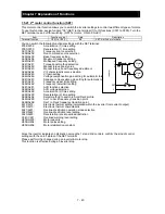
This motor control function allows you to switch the inverter settings to control two different types of motors.
To use this function, assign function "08" (SET) to the terminal [1] to [5] functions (C001 to C005). Turn the
SET terminal on and off for switching. (OFF:1st motor , ON:2nd motor )
Item Function
code Data
Description
Terminal function
C001 to C005
08
SET: Set 2nd motor data
You can switch the following functional settings with the SET terminal:
F002/F202:
Acceleration (1) time setting
F003/F203:
Deceleration (1) time setting
A001/A201:
Frequency source selection
A002/A202:
Run command source selection
A003/A203:
Base frequency setting
A004/A204:
Maximum frequency setting
A020/A220:
Multispeed frequency setting
A041/A241:
Torque boost method selection
A042/A242:
Manual torque boost value
A043/A243:
Manual torque boost frequency adjustment
A044/A244:
V/F characteristic curve selection
A045/A245:
V/f gain setting
A046/A246:
Voltage compensation gain setting for automatic torque boost
A047/A247:
Slippage compensation gain setting for automatic torque boost
A061/A261:
Frequency upper limit setting
A062/A262:
Frequency lower limit setting
A081/A281:
AVR function selection
A082/A282: AVR
voltage
selection
A092/A292:
Acceleration (2) time setting
A093/A293:
Deceleration (2) time setting
A094/A294:
Select method to switch to Acc2/Dec2 profile
A095/A295:
Acc1 to Acc2 frequency transition point
A096/A296:
Dec1 to Dec2 frequency transition point
b012/b212:
Electronic thermal setting (calculated within the inverter from current output)
b013/b213:
Electronic thermal characteristic
b021/b221:
Overload restriction operation mode selection
b022/b222:
Overload restriction level setting
b023/b223:
Deceleration rate at overload restriction
C041/C241:
Overload warning level setting
H003/H203:
Motor capacity
H004/H204:
Motor poles setting
H006/H206:
Motor stabilization constant
Since the inverter indicates no distinction among the 1st and 2nd controls, confirm the kind of control
settings with the on/off states of the SET terminal.
Please perform the change during an inverter & motor stop.
This function is effective during an inverter stop.
Motor
1
Motor
2
Inverter
U
V
W
L
SET
Summary of Contents for NES1-002LB
Page 9: ......
Page 21: ......
Page 25: ......
Page 28: ...Chapter 3 Exterior Views 3 3 ...
Page 30: ......
Page 35: ......
Page 53: ......
Page 75: ......
Page 154: ......
Page 196: ......
Page 203: ...Chapter 10 Troubleshooting This chapter describes the troubleshooting methods ...
Page 204: ......
Page 211: ......
Page 219: ......
Page 229: ......
Page 289: ...Appendix Appendix A Appendix A 1 ...
Page 290: ......
Page 292: ...Appendix Appendix 2 ...

