Chapter 7 Explanation of Functions
7 - 72
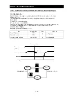
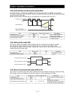
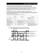
7.8.13 Communication line disconnection signal (NDc)
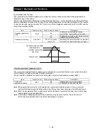
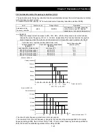
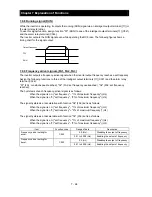
This signal function is enabled when ModBus-RTU has been selected for the RS485 communication.
If a reception timeout occurs, the inverter continues to output the communication line disconnection signal
until it receives the next data.
Specify the limit time for reception timeout by setting the communication trip time (C077).
Item
Function code
Data or range of data
Description
Terminal function
C021
32
NDc: Communication line
disconnection signal
Alarm relay terminal function
C026
Communication trip time
C077
0.00 to 99.99 (s)
Setting of the limit time for
reception timeout
7.8.14 Starting contact signal (FR)
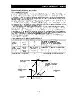
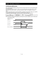
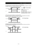
The inverter outputs the starting contact (FR) signal while it is receiving an operation command.
The FR signal is output, regardless of the setting of the run command source setting (A002).
If the forward operation (FW) and reverse operation (RV) commands are input at the same time, the
inverter stops the motor operation.
Item Function
code
Data
Description
Terminal function
C021
41
FR: Starting contact
signal
Alarm relay terminal function
C026
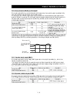
7.8.15 Heat sink overheat warning signal (OHF
) [C064]
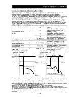
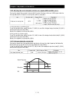
The inverter monitors the temperature of its internal heat sink, and outputs the heat sink overheat warning
(OHF) signal when the temperature exceeds the heat sink overheat warning level (C064).
Item
Function code
Data or range of data
Description
Terminal function
C021
42
OHF: Heat sink overheat warning
signal
Alarm relay terminal function
C026
Heat sink overheat warning level
C064
0. to 110. (
℃
)
Setting of the threshold
temperature at which to output the
heat sink overheat warning signal
(C077)
External control equipment
Inverter
Monitoring timer
Communication line
disconnection signal (NDc)
Communication trip time
Forward operation command
Reverse operation command
Starting contact signal (FR)
Summary of Contents for NES1-002LB
Page 9: ......
Page 21: ......
Page 25: ......
Page 28: ...Chapter 3 Exterior Views 3 3 ...
Page 30: ......
Page 35: ......
Page 53: ......
Page 75: ......
Page 154: ......
Page 196: ......
Page 203: ...Chapter 10 Troubleshooting This chapter describes the troubleshooting methods ...
Page 204: ......
Page 211: ......
Page 219: ......
Page 229: ......
Page 289: ...Appendix Appendix A Appendix A 1 ...
Page 290: ......
Page 292: ...Appendix Appendix 2 ...

