3. Piping work and refrigerant charge
72
SMGB0079 rev.0 - 01/2013
3.4 Refrigerant charge
C A U T I O N
• Do not charge OXYGEN, ACETYLENE, or other flammable and poisonous gases into the refrigerant, as an
explosion could occur. It is recommended that oxygen free nitrogen be charged for these types of test cycles
when performing a leakage test or an airtight test. These types of gases are extremely dangerous.
• Insulate the unions and flare-nuts at the piping connection part completely.
• Insulate the liquid piping completely to avoid a decreased performance; if not, it will cause sweating on the
surface of the pipe.
• Charge refrigerant correctly following the procedures of the manuals. Overcharging or insufficient charging
could cause a compressor failure.Insulate the unions and flare-nuts at the piping connection part completely.
• Check for refrigerant leakage in detail. If a large refrigerant leakage occurred, it would cause difficult breathing.
• If the flare nut is tightened too hard, the flare nut may crack after a long time and cause refrigerant leakage.
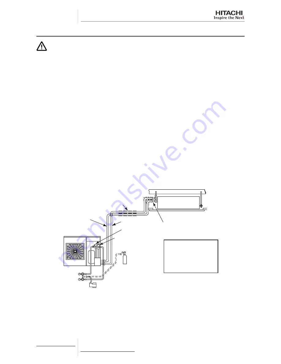
Follow the next procedure to charge the R410A refrigerant inside the indoor unit:
1
Connect the gauge manifold using charging hoses with a nitrogen cylinder to the outdoor unit check joints of the liquid
line and the gas line stop valves.
2
Supply power to the indoor unit and switch the DSW1-2 ON of its PCB1. Thereby the indoor unit SV1 and SV2 open to
allow the vacuum and refrigerant charge operation inside the indoor unit. Very important to remind to switch the DSW1-
2 OFF when finishing the whole procedure.
3
Check for any gas leakage at the flare nut connection by using nitrogen gas inside of the field-supplied piping to increa-
se the pressure at 4.15 MPa.
4
Connect the vacuum pump to the gauge manifold and operate it for 1 to 2 hours until the pressure decreases lower than
a pressure of 756 mmHg in vacuum.
5
Fully open the outdoor unit gas and liquid stop valves.
6
Operate the outdoor unit in cooling operation for more than 10 minutes to circulate the refrigerant through the whole
circuit.
Thermal insulation
Gas line
Cover the flare nut and union
of the piping connection with
thermal insulation
Liquid line
Liquid stop valve
Gas stop valve
Nitrogen tank
(For air Tight test
& Nitrogen blow
during brazing)
Vacuum cylinder
Manifold
gauge
Outdoor unit
Insulate the liquid pipe for
prevention of the capacity
decrease according to the
ambient air conditions and
the dewing on the pipe sur-
face by the low pressure
Summary of Contents for EV-1.5N1
Page 2: ......
Page 4: ... II ...
Page 26: ......
Page 100: ......
Page 144: ...5 Control System 130 SMGB0079 rev 0 01 2013 5 4 2 Dry operation Continues in the next page ...
Page 148: ...5 Control System 134 SMGB0079 rev 0 01 2013 5 4 4 Automatic cooling and heating operation ...
Page 158: ......
Page 196: ......
Page 212: ...8 Troubleshooting 198 SMGB0079 rev 0 01 2013 ...
Page 215: ...8 Troubleshooting 201 SMGB0079 rev 0 01 2013 8 ...
Page 323: ...9 Spare parts 309 SMGB0079 rev 0 01 2013 9 RAS 8 10 HNCE Spare Parts Document EPN 201211B ...
Page 332: ......
Page 452: ......
Page 479: ......


