60
Chapter
4
•
•
•
•
•
•
Step 1. Insert the USB stick into the HI 6500 series instrument
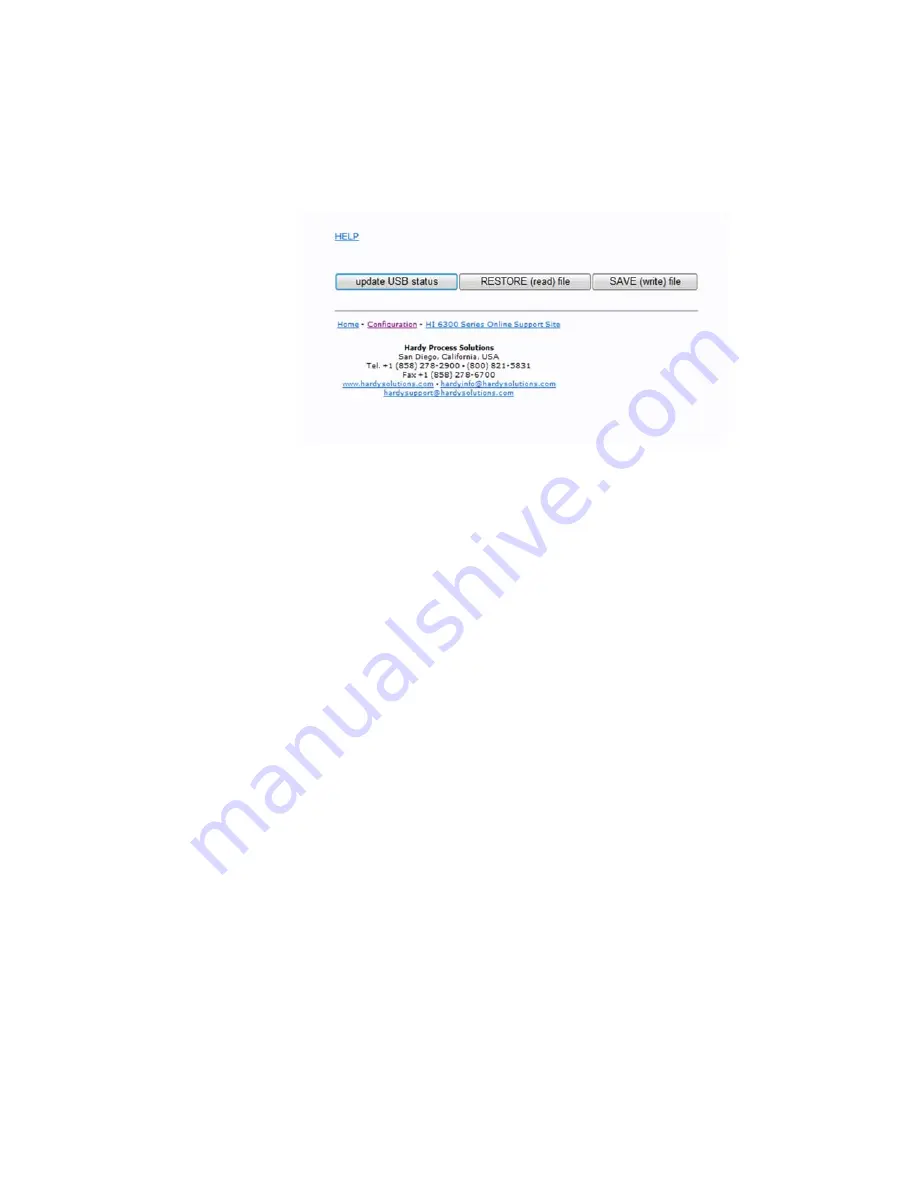
Step 2. Using the web interface or display panel, save or restore system parameters.
RESTORE Command
This command replaces the existing HI6500 or 6510 parameters by the parameters stored on a
USB memory stick. This can be used to transfer parameters from one unit to another. Users can
also create a “restore.txt” file on the USB drive that can replace the parameters on the unit by
overwriting the parameters upon a unit power up.
Users can create a “restore.txt” file by using a params.txt file created when doing a
“SAVE” function to the USB drive and copying/renaming it to restore.txt. The user can
then modify this restore file by making changes to values in the file, or even deleting
parameters. Any changed values will overwrite parameters in the unit upon power up
when the restore.txt file is present.
On the Web page
, go the communication menu and left click on the Restore button
On the HI6310 series instrument display
, select the Communication menu and use
the UP or DOWN button to select the USB submenu, then select the Restore menu item
then press the ENTER button.
SAVE Command
This command saves the current HI6500 or 6510 parameters to a USB memory stick.
The file created is params.txt.
On the Web page
, go the communication menu and left click on the Save button.
On the optional HI6110 instrument display
, select the Communication menu and
use the UP or DOWN button to select the USB submenu, then select the Save menu
item then press the ENTER button.
Summary of Contents for HI 6500 Series
Page 10: ...viii Contents ...
Page 20: ...10 Chapter 2 ...
Page 72: ...62 Chapter 4 ...
Page 96: ...86 Chapter 5 Profibus DP Commands and Parameters ...
Page 97: ...Instrument Configuration 87 Serial Option Termination ...
Page 126: ...116 Chapter 5 ...
Page 156: ...146 Chapter 8 ...
Page 163: ...Troubleshooting 153 General Troubleshooting Flow Chart Index ...
Page 164: ...154 Chapter 9 A Guideline Instability Electrical and Mechanical review ...
Page 165: ...Troubleshooting 155 A1 Checking for Unstable Components in a Weighing System ...
Page 166: ...156 Chapter 9 B Guidelines for Electrical Mechanical or Configuration Issues ...
Page 167: ...Troubleshooting 157 B1 Guidelines to Verify Electrical Installation ...
Page 168: ...158 Chapter 9 B2 Guidelines to Verify Mechanical Installation ...
Page 170: ...160 Chapter 9 C Integrated Technician and Stability Test Overview ...
Page 171: ...Troubleshooting 161 E Testing for Non Return to Zero System with IT Summing Card ...
Page 173: ...Troubleshooting 163 G Calibration Errors When Performing the Calibration ...
Page 174: ...164 Chapter 9 H Mechanical Installation ...
Page 175: ...Troubleshooting 165 J Electrical Inspection ...
Page 176: ...166 Chapter 9 K Installation Check Points ...
Page 177: ...Troubleshooting 167 M Weight Processor s Front Display is Blank or Locked ...
Page 178: ...168 Chapter 9 N Analog Out HI 6510 Only ...
Page 194: ...184 Appendix A Figure D1 Assembling the Swivel Mount Enclosure on the instrument pedestal ...
Page 196: ...186 Appendix A Dimensions ...
Page 200: ...4 HI 6500 Series USER GUIDE Index ...
Page 201: ......


