Network Configuration
41
•
•
•
•
•
•
If you do not have a Modbus PLC available to test the Modbus communications, then you
can download the Hardy Modbus Link test software from the Hardy Web site at
http://www.hardysolutions.com. This program can be found currently on the HI 4050
products page under the Docs & Programs tab.
Installing the Hardy Modbus-Link Test Package:
If you do not have a PLC or other
client, Hardy has provided the Hardy Modbus-Link Client to test communications with the
HI 6500 unit. This client package only communicates with the unit and is not a full
communications package. If you have problems with this test, contact Hardy Technical
Support. Double click the Hardy Modbus-Link .exe file to install the software on your PC.
Upon completion, a Hardy Modbus-Link icon appears on your Desktop.
Modbus services are specified by function codes that are elements of MODBUS request /
reply PDUs. MODBUS is implemented for the HI 6500 using TCP/IP over Ethernet. The
Client/Server definitions are as follows:
•
Client - The module asking for data.
•
Server - The module providing the data.
NOTE
MODBUS is positioned at level 7 of the OSI model and is accessed at a reserved system
port 502 on the TCP/IP stack. It will support communication with up to 10 different hosts
(sockets).
Configuring MODBUS
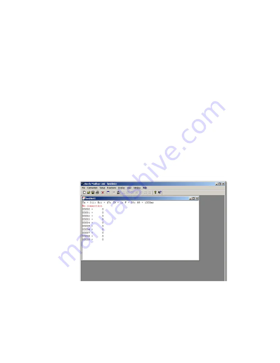
Step 1. Click the Hardy Modbus-Link icon to open the Hardy Modbus-Link display.
Summary of Contents for HI 6500 Series
Page 10: ...viii Contents ...
Page 20: ...10 Chapter 2 ...
Page 72: ...62 Chapter 4 ...
Page 96: ...86 Chapter 5 Profibus DP Commands and Parameters ...
Page 97: ...Instrument Configuration 87 Serial Option Termination ...
Page 126: ...116 Chapter 5 ...
Page 156: ...146 Chapter 8 ...
Page 163: ...Troubleshooting 153 General Troubleshooting Flow Chart Index ...
Page 164: ...154 Chapter 9 A Guideline Instability Electrical and Mechanical review ...
Page 165: ...Troubleshooting 155 A1 Checking for Unstable Components in a Weighing System ...
Page 166: ...156 Chapter 9 B Guidelines for Electrical Mechanical or Configuration Issues ...
Page 167: ...Troubleshooting 157 B1 Guidelines to Verify Electrical Installation ...
Page 168: ...158 Chapter 9 B2 Guidelines to Verify Mechanical Installation ...
Page 170: ...160 Chapter 9 C Integrated Technician and Stability Test Overview ...
Page 171: ...Troubleshooting 161 E Testing for Non Return to Zero System with IT Summing Card ...
Page 173: ...Troubleshooting 163 G Calibration Errors When Performing the Calibration ...
Page 174: ...164 Chapter 9 H Mechanical Installation ...
Page 175: ...Troubleshooting 165 J Electrical Inspection ...
Page 176: ...166 Chapter 9 K Installation Check Points ...
Page 177: ...Troubleshooting 167 M Weight Processor s Front Display is Blank or Locked ...
Page 178: ...168 Chapter 9 N Analog Out HI 6510 Only ...
Page 194: ...184 Appendix A Figure D1 Assembling the Swivel Mount Enclosure on the instrument pedestal ...
Page 196: ...186 Appendix A Dimensions ...
Page 200: ...4 HI 6500 Series USER GUIDE Index ...
Page 201: ......


