GE H
EALTHCARE
D
IRECTION
FQ091013, R
EVISION
1
V
IVID
I
N
AND
V
IVID
Q
N S
ERVICE
M
ANUAL
Chapter 3 - System Setup
3-61
3-7-5
Connecting the ECG
NOTE:
The ECG may be connected to the system at any time, whether the system is powered ON or OFF.
•
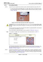
To connect the internal ECG carefully push the end of the cable connector into the ECG connector
port (circular-shaped socket on the left side of the system beside the probe connectors), as shown
in
CAUTION:
When disconnecting the ECG Cable from the Vivid
i
n/ Vivid q N,
do not pull on the cable
directly
. Carefully remove the cable by holding the outer sleeve (closest to the system) while releasing
the cable.
The same connector is used both for external and internal ECG. The appropriate ECG cable kit should
be ordered when external ECG is to be used.
See also information on Ext-ECG Module Connector provided in
Note:
For optimal ECG operation, use only electrodes that meet universal standards - see
.
Use of the External Respiratory option is enabled by removal of the ECG Board and installation of the
Internal ECG/Respiratory Board. For instructions, refer to the
ECG/Respiratory Module Assembly
Installation Procedure on page 8-17
.
NOTE:
An External ECG (Respiratory) cable should be available. This is provided by GE HealthCare (Part #
2413451 - see
Section 9-5 "Cables" on page 9-7
). Alternatively, the adaptor supplied with the GE cable
may be used to adapt an existing cable - refer to the optional connections for the External Respiratory
interface illustrated in
.
Figure 3-60 ECG Cables Connected to the ECG Connector Port
Table 3-5
ECG Cable
Description
Part No.
Full ECG Cable Kit - IEC (Europe, Asia, ROW)
2418832-2
Yellow lead (L)
Red lead (R)
Black lead (N)
Summary of Contents for Vivid in
Page 2: ......
Page 30: ...GE HEALTHCARE DIRECTION FQ091013 REVISION 1 VIVID I N AND VIVID Q N SERVICE MANUAL xxviii...
Page 739: ......


