4-4
M60 Motor Protection System
GE Multilin
4.2 EXTENDED ENERVISTA UR SETUP FEATURES
4 HUMAN INTERFACES
4
4.2EXTENDED ENERVISTA UR SETUP FEATURES
4.2.1 SETTINGS TEMPLATES
Setting file templates simplify the configuration and commissioning of multiple relays that protect similar assets. An exam-
ple of this is a substation that has ten similar feeders protected by ten UR-series F60 relays.
In these situations, typically 90% or greater of the settings are identical between all devices. The templates feature allows
engineers to configure and test these common settings, then lock them so that they are not available to users. For exam-
ple, these locked down settings can be hidden from view for field engineers, allowing them to quickly identify and concen-
trate on the specific settings.
The remaining settings (typically 10% or less) can be specified as editable and be made available to field engineers install-
ing the devices. These are settings such as protection element pickup values and CT and VT ratios.
The settings template mode allows the user to define which settings are visible in EnerVista UR Setup. Settings templates
can be applied to both settings files (settings file templates) and online devices (online settings templates). The functionality
is identical for both purposes.
Settings files conversion from previous firmware versions is supported.
a) ENABLING THE SETTINGS TEMPLATE
The settings file template feature is disabled by default. The following procedure describes how to enable the settings tem-
plate for UR-series settings files.
1.
Select a settings file from the offline window of the EnerVista UR Setup main screen.
2.
Right-click the selected device or settings file and select the
Template Mode > Create Template
option.
The settings file template is now enabled and the file tree displayed in light blue. The settings file is now in template editing
mode.
Alternatively, the settings template can also be applied to online settings. The following procedure describes this process.
1.
Select an installed device from the online window of the EnerVista UR Setup main screen.
2.
Right-click the selected device and select the
Template Mode > Create Template
option.
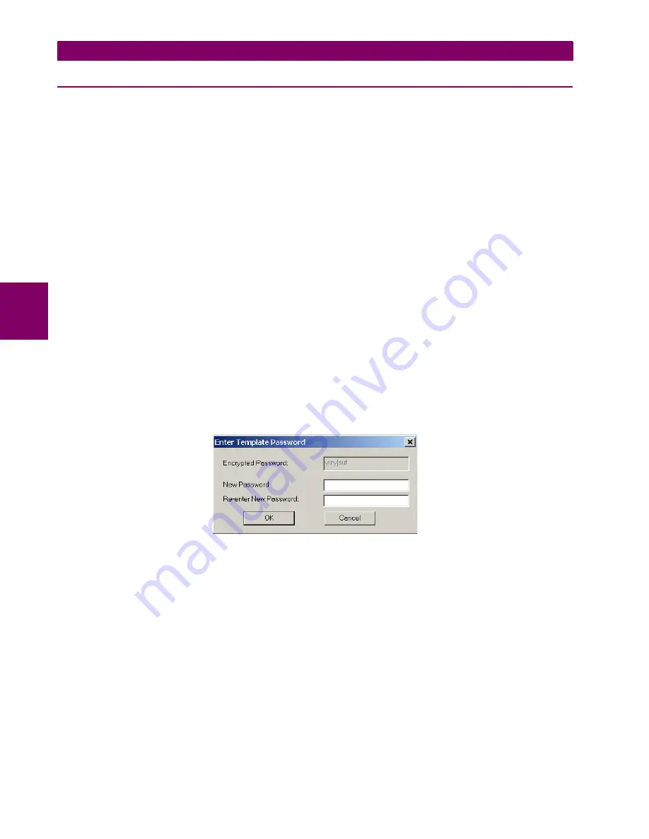
The software prompts for a template password. This password is required to use the template feature and must be at
least four characters in length.
3.
Enter and re-enter the new password, then click
OK
to continue.
The online settings template is now enabled. The device is now in template editing mode.
b) EDITING THE SETTINGS TEMPLATE
The settings template editing feature allows the user to specify which settings are available for viewing and modification in
EnerVista UR Setup. By default, all settings except the FlexLogic equation editor settings are locked.
1.
Select an installed device or a settings file from the tree menu on the left of the EnerVista UR Setup main screen.
2.
Select the
Template Mode > Edit Template
option to place the device in template editing mode.
3.
Enter the template password then click
OK
.
4.
Open the relevant settings windows that contain settings to be specified as viewable.
Summary of Contents for M60 UR Series
Page 10: ...x M60 Motor Protection System GE Multilin TABLE OF CONTENTS ...
Page 128: ...4 30 M60 Motor Protection System GE Multilin 4 3 FACEPLATE INTERFACE 4 HUMAN INTERFACES 4 ...
Page 410: ...5 282 M60 Motor Protection System GE Multilin 5 10 TESTING 5 SETTINGS 5 ...
Page 440: ...6 30 M60 Motor Protection System GE Multilin 6 5 PRODUCT INFORMATION 6 ACTUAL VALUES 6 ...
Page 452: ...7 12 M60 Motor Protection System GE Multilin 7 2 TARGETS 7 COMMANDS AND TARGETS 7 ...
Page 462: ...9 8 M60 Motor Protection System GE Multilin 9 2 BATTERIES 9 MAINTENANCE 9 ...
Page 474: ...A 12 M60 Motor Protection System GE Multilin A 1 PARAMETER LISTS APPENDIX A A ...
Page 584: ...B 110 M60 Motor Protection System GE Multilin B 4 MEMORY MAPPING APPENDIX B B ...
Page 614: ...C 30 M60 Motor Protection System GE Multilin C 7 LOGICAL NODES APPENDIX C C ...
Page 630: ...E 10 M60 Motor Protection System GE Multilin E 1 IEC 60870 5 104 PROTOCOL APPENDIX E E ...
Page 642: ...F 12 M60 Motor Protection System GE Multilin F 2 DNP POINT LISTS APPENDIX F F ...
Page 644: ...G 2 M60 Motor Protection System GE Multilin G 1 RADIUS SERVER CONFIGURATION APPENDIX G G ...
Page 652: ...H 8 M60 Motor Protection System GE Multilin H 3 WARRANTY APPENDIX H H ...
Page 662: ...x M60 Motor Protection System GE Multilin INDEX ...


