background image

FUSION SPLICER 90S Rev5 


75 


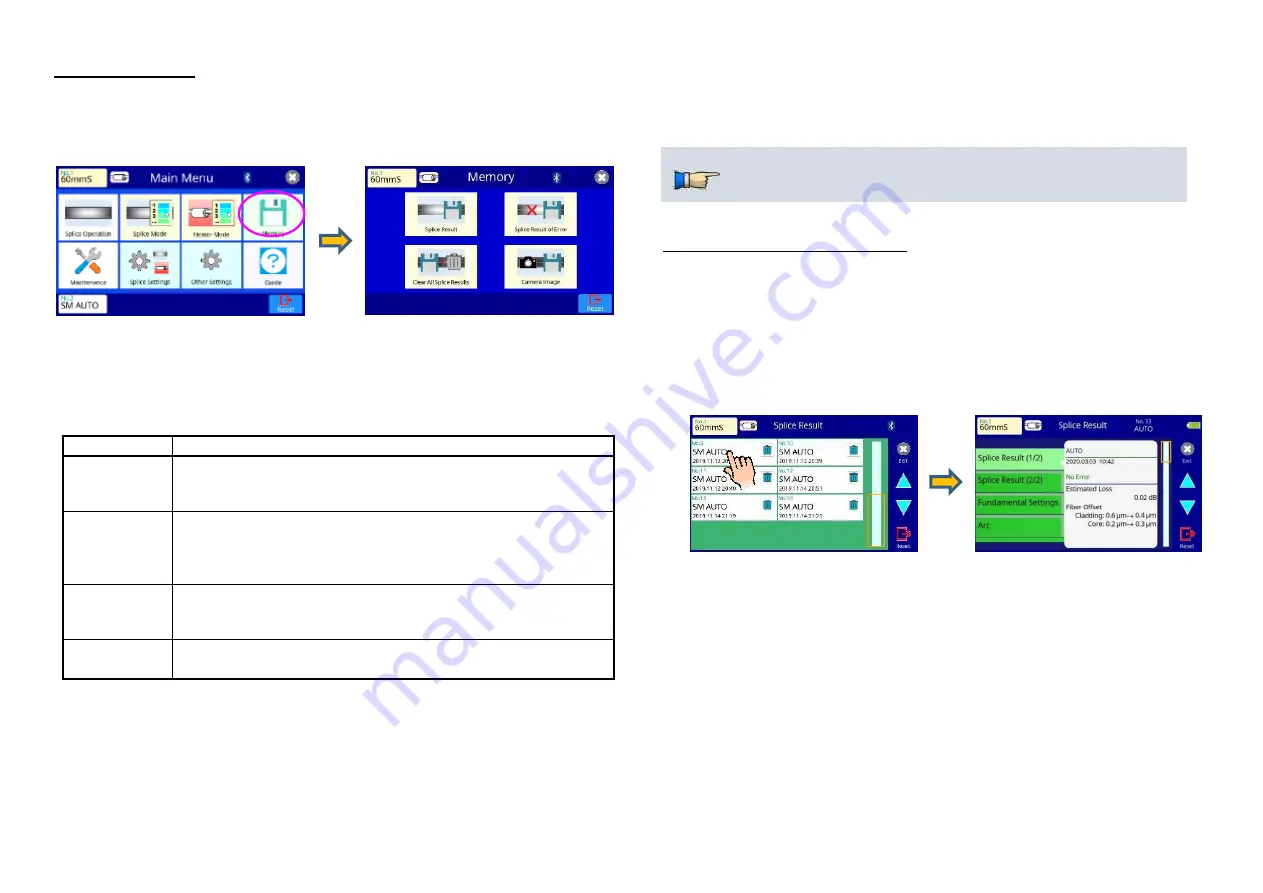
Memory Menu 

Composition of the Memory Menu 

This fusion splicer stores up to 20,000 splice results. Contents of splice data 
stored vary depending on the splice mode. 


Memory Menu Settings 

List of Memory Menu parameters


Parameter


Description


Splice Result


Up to 20,000 splice results can be stored and displayed. 
The stored data varies according to the splice mode. Selecting 
“Splice Result” enables display of all stored splice data records.


Splice Result 
of Error


Selecting “Splice Result of Errors” will display splice data 
records for only the splices in which some error message 
occurred. The error message for each splice is included in the 
available data.


Clear All 
Splice Results


All splicing results can be deleted at once.


Camera 
Image


Up to 100 camera images can be stored and displayed.


Review, editing, and deletion of splice results 

Splicing results stored in the memory can be displayed.    Comments can be 
added or edited.


Display and editing splice result data 

1. 

Select the Memory icon at the [Main Menu] screen. 
Select the Splice Results icon to display the [Splice Results] Menu. This 
enables access to all the splice data stored in memory. 

2. 

Move the cursor using the “UP” or “DOWN” arrow icon to scroll to the 
desired memory area, and then touch the screen for a specific memory 
number. This displays the detailed data for the selected splice record. 

3. 

To add or edit comments, select the target result icon to display the [Input 
Comment] screen. 


Memory Data can be downloaded by USB. 
Refer to instruction manual of “Data Connection” 

Summary of Contents for 90S

Page 1: ...ruction manual carefully before operating the equipment Adhere to all safety instructions and warnings contained in this manual Keep this manual in a safe place There is a change without a previous notice We are not responsible for the products that are not purchased from our authorized distributors ...

Page 2: ...ficult to see depending on the angle These are not defects but are characteristic of LCD monitors Caution for Air Transport This product contains Lithium Ion Battery Before shipping this product inform the transport company that this product contains the lithium Ion battery and follow their instructions Please consent beforehand The software equipped in splicer and its related documents are protec...

Page 3: ...of Splicing Quality 45 Cleaning and Checking Before Splicing 45 Periodical checking and cleaning 46 How to remove and install the Protrusion of the sheath clamp 48 Wireless data communication 50 Wireless data communication function of the splicer 50 How to establish wireless data communication 51 How to turn off the wireless data communication 52 Blade Management Menu 54 Benefit of wireless data c...

Page 4: ...he Utility Software 94 How to install the instruction manual and the Utility Software 94 Error Message List 95 Questions and Troubleshooting 100 Power Supply 100 Splicing Operation 100 Tube heating Operation 101 Wireless data communication 101 Supervising 102 Other Functions 102 Trademarks 102 Warranty and Contact Address 103 Warranty 103 Contact Address 104 ...

Page 5: ...dapter or battery In particular do not remove or bypass any electrical or mechanical device e g a fuse or safety switch incorporated into the design and manufacturing of this equipment Modification could cause damage that may result in personal injury death electric shock or fire Never operate the fusion splicer in an environment where flammable liquids or vapors exist Risk of dangerous fire or ex...

Page 6: ...no dust or dirt on the terminals Engage by pressing the female plug into the fusion splicer inlet and the male plug into the wall socket outlet until both plugs are fully seated Incomplete engagement may cause fuming electric shock or equipment damage and may result in personal injury death or fire Do not short circuit the terminals of AC adapter and optional battery Excessive electrical current m...

Page 7: ...arge It can result in equipment damage or degradation in splicing performance Do not use any chemical other than pure alcohol 99 or greater to clean the objective lens V groove LCD monitor etc of the fusion splicer Otherwise blurring discoloration damage or deterioration may result The fusion splicer requires no lubrication Oil or grease may degrade the splicing performance and damage the fusion s...

Page 8: ...ff Turn the power of the fusion splicer off in the aircraft For the optical fiber cleaver and the ribbon fiber stripper remove batteries to turn off the wireless data communication Typical wireless certifications are USA FCC Rules Part 15 FCC ID QOQ11 CANADA Industry Canada Rules RSS 247 IC 5123A 11 European Union RE directive 2014 53 EU RE Directive 2014 53 EU EN300 328 EN301 489 1 EN301 489 17 a...

Page 9: ...calibration function before splicing is not necessary It doesn t work in the special splice modes When using these modes performing Arc calibration before splicing is strongly recommended Automatic wind protector The wind protector operation can be customized by choosing the preferred operating mode for the wind protector opening and closing Fast heating system When a protection sleeve is loaded t...

Page 10: ...leaving errors given by the splicer If the splicer detects that a blade position has reached its cleave limit the splicer sends a command to the cleaver to rotate the blade to the next position By using this function the operator can maximize blade life like never before The operator can now use a cleaver without worrying about tracking blade life and can be confident they are making reliable spli...

Page 11: ...nction locks and unlocks the fusion splicer by Bluetooth communication with a smartphone It will be locked automatically if the fusion splicer is stolen Therefore it is possible to prevent unauthorized use after theft Furthermore this function may help the effect of suppressing theft The Splice smart phone application is required to use this feature Splice Pairing Unlock lock Splice ...

Page 12: ... the splice 3 Slide left hand away from the protection sleeve 4 Slide left hand away from the protection sleeve Fiber Retention Clamp The sheath clamp features a secondary clamp Fiber Retention Clamp which retains the fiber after the sheath clamp is opened This mechanism prevents the fiber from flying out after the sheath clamps open When the fiber is lifted by hand the Fiber Retention Clamp opens...

Page 13: ...re all the tools you need The work tray attached to the carrying case can be taken out The work tray can be fixed on a tripod stand to improve work efficiency Protrusion switch OFF Protrusion for loose tube Protrusion switch ON Protrusion for loose tube Open Lid of carrying case becomes a work table Remove work tray from carrying case Do not use the protrusion part when splicing standard fiber Onl...

Page 14: ...e work tray has a stand to place the protection sleeve after heating Protection sleeve stand can be detached Drop cable holding stand The work tray has a stand for placing the drop cable clamp CLAMP DC 12 The stand has two positons One is the position during splicing Another is the positon during heating Stripper SS03 Cleaver CT50 Battery BTR 15 up to 2 units Work tray Push apart For heating For s...

Page 15: ...menu appears The operator can now use the fusion splicer like previousfusion splicers Touchscreen Calibration Touch detection accuracy of the touchscreen were adjusted in the factory before shipping However the accuracy could change due to various reasons If the response of the touchscreen is not good adjust it according to the following procedure Adjustment procedure Press DOWN key in READY scree...

Page 16: ...o charge all smartphones Connector type Current capacity USB 2 0 Type A Max 0 5A When the fusion splicer battery is used to power other devices the number of splice and heat cycles will be reduced When the remaining battery power is low the power supplied to external devices will become unstable Connecting a device outside the above specifications may affect splicing behavior When the behavior of ...

Page 17: ...ce Guide QRG 02 E Optical Fiber Cleaver CT50 Wireless PC Clamp Setting Guide SG 03 E Warning and Cautions WAC 01 E Single Fiber Stripper SS03 Core Alignment Fusion Splicer 90S Carrying Case CC 39 AC Adapter ADC 20 AC Power Cord ACC xx USB Cable USB 01 Electrodes spare ELCT2 16B Fiber Holder Set Plate SP 03 Work Table Left WT 08L Work Table Right WT 08R Work Table J Plate JP 09 Battery Pack BTR 15 ...

Page 18: ...Fiber coating diameter UV coating 250µm Nylon coating 900µm Fiber holder Optional FH 70 250 Old model FH 60 250 can also be used FH 70 900 Old model FH 60 900 can also be used Fiber protection sleeves optional Standard sleeve 60mm length FP 03 FP 03M 40mm length FP 03 L 40 ...

Page 19: ... 90S Rev5 18 Description of Splicer Structure 90 LCD monitor Tube heater Wind Protector USB port Mini USB port A Ribbon Stripper terminal Wind protector Power unit dock External terminal Top view Front view Side view ...

Page 20: ...groove illumination LED LED Inside of Wind protector Electrode Electrode V groove V groove V groove Clamp V groove Clamp Sheath Clamp Fiber Retention Clamp Fiber Retention Clamp Switch Fiber Retention Clamp Switch Fusion work area ...

Page 21: ...pped if the HEAT key is pressed again when the LED is blinking RESET key Regardless the splicer s status RESET stops any function except the tube heater heating process After pressing the splicer will return to the ready state with a beep sound SET key Starts the splicing operation or progresses through a PAUSE state UP DOWN arrow keys These arrows are used to move the cursor for navigating the me...

Page 22: ...ve the fusion splicer from carrying case and put on top of the lid Arrange safety belts devices for equipment and accessories on the tray before use Straps for small accessories may be recommended If the equipment accessories were dropped on a person under splicing work area this could result in a serious injury or fatal accident Do not operate the fusion splicer in an unstable or unbalanced posit...

Page 23: ... place Detaching power supply Turn off the fusion splicer before removing the power unit Take the cover off and then hook a finger on the bottom of the power supply unit and remove the power supply unit from the fusion splicer body AC Operation 1 When operating the fusion splicer with AC power use AC adapter ADC 20 and AC power cord ACC xx or either Power Unit of the following Battery Pack BTR 15 ...

Page 24: ...otection circuit in DCA 03 or BTR 15 shuts down the DC output DC cord DCC 20 DC cord DCC 21 Car Cigar socket to BTR 15 or DCA 03 Car battery to BTR 15 or DCA 03 Adhere to below practices to prevent battery damage The charge of the battery pack after air transport may be 30 or less in accordance with the aviation law When it arrives please charge the battery pack to full The capacity of the battery...

Page 25: ...ery charge and is affected by environmental conditions and battery quality If splicing on battery power we recommend fully charging the battery before operating How to check remaining battery capacity by the battery pack If battery is not inserted in the splicer simply press the battery check push button on the battery pack The remaining battery capacity is indicated on the LED indicator Remaining...

Page 26: ...pply terminal of AC adapter and AC power cord The battery can be charge while splicer is in use Installed BTR 15 into power dock and then connect to AC adaptor ADC 20 or DC power cord AC adapter AC power cord Battery pack The battery pack can be charged with AC and DC Do not place battery on top of AC adapter or vise versa The battery can be charge while the fusion splicer is in use Installed BTR ...

Page 27: ...is then identified If the battery is used the remaining battery capacity is displayed Turning Fusion Splicer OFF Press ON OFF key and hold until the red LED turns off and then detach When the power is off but the sheath clamp is open the wind protector may not close and the display shows the message below In this case please close the sheath clamp and turn off the power by pressing the ON OFF key ...

Page 28: ... function in Maintenance can be selected directly 7 Arc Count The number of arc discharges in Maintenance is displayed 8 Splice Mode Current Splice Mode is displayed After touching the Splice Mode screen appears immediately 9 Main Menu After touching the Main Menu screen appears 10 Reset This is RESET key The function is as same as RESET key on the sheet key 11 Help This is HELP icon This function...

Page 29: ...e SET key to set the value Wireless communication with tools When the cleaver or the ribbon fiber stripper has been paired to the fusion splicer the fusion splicer and tools start wireless communication automatically After connecting the status icons is displayed on the monitor Wind protector automatic opening and closing function If the OPEN CLOSE key is pressed at the READY screen the wind prote...

Page 30: ...ng automatically after setting fibers on left and right sides After splicing If press SET key proof test and wind protector opening are simultaneously done Perform sheath clamp opening manually manual Before splicing If press SET key start splicing After splicing If press SET key proof test and wind protector opening are simultaneously done Perform sheath clamp opening manually A continuation of t...

Page 31: ...to change the operation mode Touch the Main Menu icon on Ready screen a Main menu screen will be displayed Touch the Splice setting icon to enter the Splice setting screen and touch the Operation mode to select the favorite operation ...

Page 32: ...eters can be edited for a specific fiber combination How to check the splice mode The current splice mode is displayed in the monitor as shown below How to change the splice mode Select an appropriate splice mode for type of fiber to be spliced 1 Select Splice Mode icon at READY state The Splice Mode screen appears 2 Select the suitable splice mode in the list 3 The color of the selected icon chan...

Page 33: ...r Splice of a drops cable FUSE2 3 ST FC For Fuse connect splice FUSE900 SC LC ST FC FUSE2 3 SC LC 40mmR FP 05 For standard 40mm protection sleeve Such as Fujikura FP 05 protection sleeves 40mmR FP 04T For standard 40mm protection sleeve Such as Fujikura FP 04T protection sleeves 28mmR FPS 08 28 For standard 28mm protection sleeve Such as Fujikura FPS08 28 protection sleeves 30mmR FPS 04 30 For sta...

Page 34: ...n the READY screen If you press these Heater Mode icons enter to Heater Mode screen directly When using a protection sleeve that is not made by Fujikura please set parameters based on the specific sleeve When the sleeve of another company is used the durability of a protection point cannot be warrantied ...

Page 35: ...int free tissue thoroughly Frequently replace cleaning gauze to insure splice quality Fiber Cleaving when using a sheath clamp 1 Take out the CT50 from the carrying case and release the lock from the lever 2 Lift the lever until it stops The blade is automatically set at the start position and is now ready to cleave the fiber 3 Open the lid of the fiber plate AD 10 M24 Set the cleaned fiber onto t...

Page 36: ...f the fiber Fiber Cleaving when using a Fiber Holder Install the Fiber holder set Plate SP 03 1 Loosen the 3 screws and remove each sheath clamp from the fusion splicer 2 Attach the Fiber holder set plate SP 03 on the base and tighten 3 screws 3 Set the fiber onto the fiber holder and close the lid of the fiber holder Methods of setting the fiber are as follows Do not put fingers in the cleaving a...

Page 37: ...ruded nose of the fiber holder In case of Fiber holder FH 60 series Set the fiber in the fiber holder with the fiber coating 3 0mm from the edge of the fiber holder Fiber Cleaving 1 Lift the Lever until it stops The blade is automatically set at the start position and is now ready to cleave the fiber Select a suitable fiber holder based on the fiber coating diameter If fiber coating has some memor...

Page 38: ... Open the wind protector and sheath clamps 2 Place prepared fiber onto v groove so that the fiber tip is located between the v groove edge and tip of electrode 3 Hold fiber with fingers and close sheath clamp so that the fiber does not move Make sure the fiber is placed in the bottom of the v grooves If fiber is not placed properly reload fiber The prolonged storage back and when splicing for the ...

Page 39: ...nges with ON OFF of a proof test setup in splice mode Arc Calibration Atmospheric conditions such as temperature humidity and pressure are constantly changing which creates variability in the arc temperature This fusion splicer is equipped with temperature sensor that is used in a constant feedback monitoring control system to regulate the arc power at a constant level Changes in arc power due to ...

Page 40: ...forward motion stops at a certain position shortly after the cleaning arc is performed 2 Next the cleave angle and fiber angle are checked If the measured cleave angle is greater than its set threshold or fiber chipping is detected the buzzer will sound and an error message warns the operator In some cases multiple iterations of arc calibration are needed until the calibration process is successfu...

Page 41: ...ischarge re arc Splice loss estimate and splice check are performed again The pause after cleave angle check and fiber alignment can be disabled See section Splice Settings for detail The cleave angle threshold can be changed See section Splice Menu The cleave angle error message can be ignored by pressing SET key to go on to the next step To disable the cleave angle error See section Splice Setti...

Page 42: ...fuse time too short Increase Prefuse Power and or Prefuse Time Splice loss increase Cause and remedy 2 of 2 Symptom Cause Remedy Separation Fiber stuffing too small Perform Motor Calibration Prefuse power too high or prefuse time too long Decrease Prefuse Power and or Prefuse Time Fat Fiber stuffing too much Decrease Overlap and perform Motor Calibration Thin Arc power not adequate Perform Arc Cal...

Page 43: ...aracters 3 In the case of Password input the next screen image is displayed if the correct password is input If the input password is incorrect the previous screen image is displayed Fiber proof test The strength of the splice point can be checked After splicing a proof test is performed by pressing the SET key or opening wind protector If the operation mode is set to Auto or Auto LR a proof test ...

Page 44: ... protection sleeve over the splice point 1 Splice finishes and wind protector opens Fiber retention clamp holds fiber 2 Hold the left fiber at the end of sheath clamp shown below 3 Tilt the fiber to slide the protection sleeve toward the left while maintaining tension 4 The protection sleeve slides and reaches your left hand 5 Slide your left hand left Keep your right hand in the same position 6 M...

Page 45: ...he lid automatically opens and you can remove fiber from the heater Visually inspect the finished protection sleeve to verify no bubbles or debris dust is present in the protection sleeve Notes at the time of a protection sleeve set Apply tension until heater holds the fiber If you release tension before the lid closes If HEAT key is pressed during tube heating the HEAT LED blinks If HEAT key is p...

Page 46: ...ottom of the V groove Repeat step section 2 after this procedure Cleaning V groove Clamp Chips If contaminants are present on the clamp chips proper clamping may not occur resulting in poor quality splices The v groove clamp chips should be frequently inspected and periodically cleaned during normal operation To clean the clamp chips do the following 1 Open the wind protector 2 Clean the surface o...

Page 47: ...hat has 16 positions Each position can cleave approximally 1 250 fibers The blade can be rotated automatically or manually Automatically rotate When the wireless data communication function of the splicer is on the splicer analyzes the cleaving end face in relation to the current blade position Then the splicer judges the cleaver blade worn if several errors occur in a short period and automatical...

Page 48: ...The Blade height can be changed by rotating the Blade Height Dial located on the front of the cleaver It can be raised a total of two times Method 1 Verify the position of the Blade Height Dial 2 Rotate it to next number Do not rotate more than one position at one time Replace the blade after raising it 2 times and after all 16 positions have been used The Cleave Blade and Arm set for CT50 is user...

Page 49: ... Fujikura authorized distributor How to remove and install the Protrusion of the sheath clamp The sheath clamp is equipped with a protrusion for loose tube fiber The protrusion pinches the loose tube fiber against the tight buffer fiber within However it may damage other types of fiber coating If you do not splice loose tube fiber you can remove it with following procedure How to remove 1 Remove t...

Page 50: ...hite plastic part to make a space for the spring as below photo while keeping to not fall After placed the spring adjust the position with tweezers as below so each spring edge fit the convex of clamp and concave of white part 5 Put the big plastic part in the pot of the clamp while keeping pressing down the small plastic part with tweezers 6 Place the metal plate and fix by two self tapping screw...

Page 51: ...en paired with a device the icon of each tool appears on the right side of the LCD monitor Selecting each icon takes you to its user menu icon Description When the Splicer in Bluetooth menu is set ON this sign appears Press this icon to enter the Bluetooth menu in Other Setting directly This icon shows the status of the paired cleaver 1 Serial Number 2 Battery capacity 3 Remaining of Blade life 4 ...

Page 52: ...e splicer to the cleaver and ribbon fiber stripper via Bluetooth are on the next page After initial pairing those machine are always paired communication between splicer cleaver and stripper resumes automatically even after power cycling However when Bluetooth is turned off on either device communication of cleaver data ceases Procedure 1 Turn the splicer power on 2 Place batteries in the cleaver ...

Page 53: ...onds of cleaver or ribbon fiber stripper The Link LED will begin blinking blue and then wait for the command from the splicer to pair 4 For each unique device it adds the serial number to the Device List screen 5 Touch the serial number on screen of the cleaver or the ribbon fiber stripper you want to connect to 6 This initiates the wireless data communication with the new ribbon fiber stripper or...

Page 54: ...r Ribbon Fiber Stripper Procedure1 1 Press and Hold the Link button on the RS02 RS03 for 6 seconds 2 The blue LED light turns off Now wireless data communication has ceased On the pairing screen of the splicer Paired is displayed but wireless communication can t be used unless it is reestablished If you want to reestablish wireless communication refer to the previous procedure on establishing wire...

Page 55: ... by touching the monotor Benefit of wireless data communication function Convenient usage with cleaver CT50 1 It is difficult for operators to track blade wear However it is easy to detect blade wear by correlating blade positions with cleaving errors given by the splicer If the splicer detects that a blade position has reached it s cleave limit the splicer sends a command to the cleaver to rotate...

Page 56: ... diameter can be stripped with this ribbon fiber stripper The fusion splicer also wirelessly communicates with RS02 RS03 The ribbon fiber stripper settings are automatically changed according to the splice mode To simplify field work the operator can change the heat setting of the RS02 RS03 at any time with the fusion splicer ...

Page 57: ...plains how to set the Smart Lock Procedure 1 Press the Bluetooth Icon at the READY screen to open the Bluetooth Menu Set Splicer setting to ON 2 Select Paring With Splice menu and set Splice setting to ON 3 Tap the splice icon in your smartphone Then select the FUSION SPLICER in the Splice 4 Select the Pairing With Splice in the splicer Then press Set key 5 Wait until the splicer shown is in the S...

Page 58: ...In case you change smartphone to new one or lose etc 1 Press the SET button when the splicer shows below message shows 2 Turn the Splice on and select the FUSION SPLICER in the Splice 3 Press the SET button in the splicer and start pairing 4 Wait until the splicer shown is in the Splice Tap the icon Icon color will change Light blue when pairing finished 5 Input the password in the Splice Then the...

Page 59: ... Memory Memory screen appears This allows review of the splice result or to change comments Maintenance Maintenance Menu screen appears This allows review of the splicer condition Splice Settings Splice Setting screen appears This allows review edit of splice parameters and motion of the splicer during the operation A continuation of icon list Icon Name Description Other Setting Other Setting scre...

Page 60: ...harge Parameters for calculating estimated splice loss Parameters for controlling fiber alignment and splicing procedures Threshold for error messages A series of optimal splice parameters for major fiber combinations are already stored in the splicer These parameters are stored in the database area and can be copied to the user programmable area These splice parameters can be edited for a specifi...

Page 61: ... BIF ITU T G657 and MMF ITU T G651 This mode uses the standard parameters Therefore the splice loss may be higher than another Auto mode If the fiber type is identified uses the specific Auto mode SM AUTO This splice mode can splice standard SM fiber MFD 9 to 10µm Wavelength 1310nm ITU T G 652 MM AUTO This splice mode can splice the standard MM fiber Core diameter 50 0µm 62 5 µm ITU T G 651 NZ AUT...

Page 62: ...high yield to consistent splice loss Automatic arc calibration doesn t work in this splice mode With this mode selected perform the Arc Calibration manually before splicing Database of splice mode Fast Splice mode Description SM FAST For splicing standard Single mode fiber ITU T G652 The MFD is 9 to 10 um at wavelength of 1310 nm Automatic arc calibration doesn t work in this splice mode Execute A...

Page 63: ...alue and a finishing core offset value Set Start Offset manually and then splicing starts Re arcing is performed continuously automatically until the axial offset reaches Stop Offset value A splice loss estimate is not performed Editing Splice Mode Splicing parameters in each splice mode can be modified Arc power and Arc time are considered the two most vital parameters To edit parameters follow t...

Page 64: ...s are overwritten by the factory value in the database Creating or deleting splice modes How to create a splice mode There are a standard set of splice modes listed when the splicer is first shipped and all the other modes are displayed BLANK Follow the steps below to add a splice mode 1 Select a BLANK splice mode that is gray in Splice Mode screen 2 Change Fiber Type to the splice mode in the dat...

Page 65: ...SION SPLICER 90S Rev5 64 How to erase splice mode Splice mode can be erased Follow the below steps to erase a splice mode 1 Press icon of the mode to be erased 2 Select Fiber Type and change it into BLANK ...

Page 66: ...Arc A cleaning arc burns off microscopic dust particles on the surface of the fiber with an arc discharge for a short period The duration of the cleaning arc can be changed by this parameter Arc Power Arc Power is fixed at STANDARD Arc Power is changed automatically Arc Time Arc Time is fixed at 2000ms This is automatically changed depending on the cladding illumination during Arc Discharge Parame...

Page 67: ...me of aligning and pre fusion discharge Gapset Position Sets the relative position of the splicing location to the center of electrodes Splice loss may be improved in the case of dissimilar fiber splicing by shifting Gapset Pos towards a fiber whose MFD is bigger than the other fiber MFD Parameter list 2 of 5 Parameter Description XY Aignment Focus L R Sets the focal point for fiber observation Th...

Page 68: ...ing Arc2 discharge arc power can be pulsed by turning the arc on and off This sets the amount of time that Arc2 is ON Arc2 Off Time Sets Arc2 OFF Time during Arc2 When the Arc2 discharge is intermittent re arc discharge is also intermittent When continuous re arc discharge is necessary set this parameter to OFF Parameter list 4 of 5 Parameter Description Tapering Taper Splice Splice loss is someti...

Page 69: ...per if Heater Parameter Control in Stripper Setting menu is set to Splice Mode See the detail in Bluetooth section Heat Finish Time Manual Splice Mode This mode is to manually align and splice fibers The following procedure is required and is different from standard automatic splicing 1 Select a splice mode that allows the splice parameter Align in page two of splice mode edit menu to be changed t...

Page 70: ... splices fibers AT1 mode provides an estimated splice loss but this should be regarded as a reference as the estimated splice loss may not be correct in some cases depending on fiber properties A power meter is recommended for correct splice loss measurements Parameter Description Target Loss Sets target splice loss Coefficient If actual splice loss measured does not match Target Loss the coeffici...

Page 71: ...nce length of 5 mm or less mmS FPS01 400 400 or less um of diameters of coating In addition there are 20 25 and 34 or 40 mm length 20mmS FPS01 900 20 900 or less um of diameters of coating Splice of the interference length of 6 mm or less mmS FPS01 900 900 or less um of diameters of coating In addition there are 25 and 34 or 40 mm length 60mmS FPS01 DC 60 For Splice of a drops cable FUSE2 3 ST FC ...

Page 72: ...m The dimensions of the protection sleeve after shrink vary depending on the diameter of the fiber Referring to or Editing Heater Mode Tube heating conditions stored in heater mode can be edited or changed 1 Select the icon in the Heater Mode menu to show the heater mode The settings category is displayed on the left side The parameters included in the category are displayed on the right side 2 Se...

Page 73: ...he target parameter 3 Select the parameter displayed on the right side to show the parameter edit screen 4 Select and change the target parameter Creating and Deleting Heater Mode Creating heater modes There are necessary heater modes stored when the fusion splicer is first delivered and all the other modes are displayed BLANK Follow the steps below to add a heater mode 1 Select BLANK icon which c...

Page 74: ...of the monitor during the splicing heating process Max number of characters used is 7 Mode Title2 Description of a heater mode in the Sleeve Type screen Max number of characters used is 15 Heat Time Sets heating time from the beginning to the end cool down completion Heating time is automatically adjusted with atmospheric conditions such as ambient temperature Heating time may be longer or shorter...

Page 75: ...ving the right clamp of the heater is required Remove heater clamp Loosen the screw on the right side of the heater and remove the clamp with a screwdriver This allows you to place the splice on connector in the tube heater using the connector holder To reinstall press down on the connector holder from the top so it is secure against the fusion splicer body and reinsert the screw on the right side...

Page 76: ...le data Clear All Splice Results All splicing results can be deleted at once Camera Image Up to 100 camera images can be stored and displayed Review editing and deletion of splice results Splicing results stored in the memory can be displayed Comments can be added or edited Display and editing splice result data 1 Select the Memory icon at the Main Menu screen Select the Splice Results icon to dis...

Page 77: ... the section above for how to delete data Clear All Splice Results All splicing results can be deleted at once 1 Select the Clear All Splice Results icon in the Memory Menu 2 Press the Execute icon to confirm and delete all splice results data Camera Image This function is used to store the fiber image after splice or error occurred A total of 100images can be stored 1 Select the Camera Image icon...

Page 78: ... is used in a constant feedback monitoring control system to regulate the arc power to a constant level Changes in arc power due to electrode wear and glass adhesion cannot be corrected automatically Also the center position of arc discharge sometimes shifts to the left or right In this case the fiber splicing position has to be shifted in relation to the arc discharge center It is necessary to pe...

Page 79: ... entered inside the optical path Please contact the nearest Fujikura authorized distributor for additional instructions 3 The dust check and motor calibration functions exist as independent instructions in Maintenance Menu It is possible to execute them independently Check Item Description LED Check Measures and adjusts the brightness of the illumination LED Dust Check Checks the optical path for ...

Page 80: ...bers in the fusion splicer and press SET key 3 Speeds for all motors are automatically calibrated Upon completion Maintenance Menu is displayed Stabilize Electrodes In the event of sudden change in environmental conditions the arc power may become unstable resulting in higher splice loss This is especially likely to happen when the fusion splicer is moved from lower elevations to higher elevations...

Page 81: ...the Good message appears For details of the arc calibration process see section Arc Calibration Clear Arc Count This function enables the stored number of arc discharges to be reset 1 Select the Clear Arc Count icon 2 When the confirmation screen Is it OK to clear appears press SET key to clear Clear Cleaver Counter This function resets the number of cleaves stored in Maintenance Info During the w...

Page 82: ...n Software License page appears When selecting Maintenance Info the following information is displayed Parameter Description Serial Num Displays the serial number of the fusion splicer Version Displays the software version Arc Count Displays the number of arc discharges since electrode replacement Performing the function Replace Electrodes or Clear Arc Count resets this parameter to zero Total Cou...

Page 83: ...tomated wind protector has several operation modes Pause1 If Pause1 is set to ON the splicing operation pauses when fibers are forwarded to gap set position Cleave angles are displayed during the pause Pause2 If Pause 2 is set to ON the splicing operation pauses after fiber alignment is completed With ECF ON core to core alignment is made after this pause Splice Memory Comment A comment can be add...

Page 84: ...or shown on the left by pressing the SET key Disable An operator can t bypass an error shown on the left Bubble Fat Thin Cleave Angle Set to Enable or Disable Enable An operator can accept and continue with the error as shown on the left by pressing the SET key Disable An operator can t override the error as shown on the left The unit repeats the alignment when the operator presses the SET key Cle...

Page 85: ...ng and maintenance parameters in this menu follow Parameters List of the Machine setting menu 1 of 3 Parameter Description Basic Settings Language Select the language displayed on the screen The language that can be displayed is controlled by the software version and region code Buzzer Volume Sets the Buzzer Volume level Monitor Position Sets the operational direction of splicer Front is for front...

Page 86: ...splices can be made with a Caution displayed If the value is exceeded an alarm will be displayed Electrode Warning The number of times splices can be made with a Warning displayed If the value is exceeded an alarm will be displayed Alarm Display during Reset If set to ON the warning text will be displayed during RESET operation Parameters List of the Machine setting menu 3 of 3 Parameter Descripti...

Page 87: ... calendar Password Setting Supervisor Password Sets a password to access the Supervisor Settings menus Maximum Characters 9 At the time of shipment from factory the password is set to 0 In the event you have forgotten your password contact the nearest Fujikura authorized distributor Boot Password Changes the password to access the Boot password The default password is set to 0 when the splicer is ...

Page 88: ...word 11 LL Boot Password Lock From 11 2020 03 01 Boot Password 12 MM Boot Password Lock From 12 2020 04 01 If the present date date of splicer operation is between 2019 09 01 and 2019 9 30 the splicer displays Enter Boot Password 4 at boot up Inputting EE unlocks the splicer in this case NOTE1 It is not necessary to input dates in order The splicer sorts the passwords by date In this example the s...

Page 89: ...e Operation Setting to Disable prevents unauthorized editing of the Splice Settings menu Fiber image on Screen Ignore Splicing Error Other splice Settings Machine Settings Basic Settings Setting to Disable prevents unauthorized erasing of splice result data from memory Power Saving Timer Power On Option Electrode Cleaver Blade Alarm Arc Calibration The list of Menu Lock Settings parameters 2 of 2 ...

Page 90: ...eters Parameter Description Splicer Turns the wireless data communication function of the splicer ON OFF Cleaver Toggles ON OFF the wireless data communication with the CT50 Paring With Cleaver Indicates the status of the wireless data communication Use this function to select the specific wireless cleaver as the splicer can pair with 2 cleavers Stripper Turns the wireless data communication with ...

Page 91: ...yed for the operator when required Blade Height Change Blade Replacement Blade Alarm Detection Selects the judgment criteria for the cleaver blade wear and blade rotation alarm according to the following three options Cleaving Count Rotation alarm is based on the number of cleaved fibers at the current blade position Image Analysis Rotation alarm is based on the number of cleaving errors that occu...

Page 92: ... rate of bad cleaving According to the graph the rate increases gradually The recommended threshold value for determining an expanded position is below Number of Cleaving Errors 3 times Number of Cleavers 10 times 1000 1500 2000 Occurrence ratio of bad cleave Detect line Cleaving count ...

Page 93: ...r The fusion splicer controls the ECO mode of RS02 03 with parameters that set into the memory of fusion splicer ECO Mode Toggles ECO mode ON OFF Note This parameter is disable when selecting the Splicer on ECO Mode Control by Temperature Keeping Sets the time delay before ECO mode initiates Buzzer Settings Buzzer Volume Sets buzzer volume and under what conditions it is activated Power On Only RS...

Page 94: ...on Heater Condition Setting List of the reference guide 2 of 2 Splice with Sheath Clamp Necessary items Describes the tools and procedure of splicing and tube heating with sheath clamp Preparation Splice operation Protecting Splice Point Splice with Fiber Holder Necessary items Describes the tools and procedure of splicing and tube heating with fiber holder Preparation Splice operation Protecting ...

Page 95: ...the Windows Explorer on the PC You will find an attached drive named SPLICER and a file named Install or Install bat on the drive 4 Right click on Install or Install bat then select Run as administrator in the pop up window If a confirmation message appears click Yes to continue the installation 5 The utility software opens automatically after the installation Shortcut icons for the instruction ma...

Page 96: ...TO mode L R Bad Fiber Position When an error is in the list below the fusion splicer carries out operation which changes with preset values of Ignore Splicing Error when the operator presses the SET key See Section Splice Settings Large Cleave Angle Cleave Shape NG Thin Fat Bubble Dust Burned High Loss Estimated Follow the solution precisely as shown in the list below If it is not possible to elim...

Page 97: ...ct core fibers Auto or the correct focus value should be entered R Too Dusty Fiber Error Message List 2 of 8 Error Message Reason Solution ZL Motor Overrun Forward The fiber is not set correctly at the bottom of the V groove The fiber is not located in the Camera s field of view The cleave length bare fiber part is too short Press RESET key and set the fiber again to seat it correctly at the botto...

Page 98: ... and Prefuse Time settings in the splice mode L R Bad Fiber Position The fiber is not set correctly at the bottom of the V groove Press RESET key and re position the fiber again to seat it correctly at the bottom of the V groove Error Message List 4 of 8 Error Message Reason Solution No Arc Discharge Arc Discharge did not occur Assure the electrodes are in proper position Replace the electrodes Co...

Page 99: ... normal splice mode the prefuse is fixed and cannot be adjusted Error Message List 6 of 8 Error Message Reason Solution Large Dust Burn Bad fiber end face Check the condition of the fiber cleaver If the blade is worn rotate the blade to a new position Cleaning Arc time is too short or OFF Dust still present after cleaning fiber or cleaning arc Clean fiber thoroughly or Increase Cleaning Arc Time H...

Page 100: ...t 8 of 8 Error Message Reason Solution There is dust after executing Dust Check function Dirt or dust exists in optical path Clean the objective lenses by referring see section Cleaning of Objective Lens When the above processes cannot remove the dirt or dust consult the nearest Fujikura authorized distributor X Camera Y Camera Trouble The Camera may be damaged Consult the nearest Fujikura authori...

Page 101: ...oss error message section in the Error Message List If the fiber has curl or bend memory position the fiber so the crown curve of the memory is turned downward The splice loss varies according to the cleave angle arc conditions and fiber cleanliness If the splice loss is still too high or inconsistent after performing the above mentioned remedies contact the nearest Fujikura authorized distributor...

Page 102: ...ned off if the HEAT key is pressed again If after 2 seconds have gone by without pressing the HEAT key again the LED stays on continuously and the heater returns to its normal state The LED will turn off when the heat cycle is completed If the heater does not reach the current mode s temperature value the LED blinks and the alarm sounds If this happens contact the nearest Fujikura authorized distr...

Page 103: ...ter replacing the electrodes or when the environmental conditions change drastically The number of arc calibrations can be set to a specific amount When the fusion splicer completes the set amount of calibrations it indicates Test Finish However this does not mean it is completely calibrated 3 Test Finish is never indicated after many repetitions in Arc Calibration Execute Stabilize Electrodes fun...

Page 104: ...using 8 Serial number is incorrect or not recorded serial number at Fujikura 9 Travel expense for a trip of repairing requested by customer 10 Shipping cost for repairing product 11 In case this product was resold leased or transported outside the country where the authorized Fujikura distributor sold it 4 Information required for repairing If you have any questions for repair contact the nearest ...

Page 105: ...ww fujikura co uk AFL 260 Parkway East Duncan SOUTH CAROLINA 29334 U S A General inquiries 1 800 235 3423 Service support 1 800 866 3602 P O Box 3127 Spartanburg SC 29304 3127 URL https www aflglobal com Fujikura Asia Ltd 438A Alexandra Road Block A Alexandra Techno Park 08 03 SINGAPORE 119967 General inquiries service support 65 6 278 8955 URL https www fujikura com sg Fujikura Ltd 1 5 1 Kiba Kot...

Reviews: