25 A/D CONVERTER (ADC10)
25-6
Seiko Epson Corporation
S1C33L26 TECHNICAL MANUAL
The results of A/D conversion are stored in ADD[15:0] each time conversion in one channel is completed. At the
same time, a conversion completion interrupt can be generated, enabling to read out the converted data. If no con-
version completion interrupt is used, read the conversion results from ADD[15:0] after confirming that ADCF is set
to 1 indicating completion of conversion. ADCF is reset to 0 when ADD[15:0] is read.
When a single channel or multiple channels are being converted continuously, the conversion results must be read
out from ADD[15:0] before the following conversion has completed. If the A/D conversion currently underway is
completed while ADCF is set to 1 (before reading the previous conversion results), ADD[15:0] is overwritten and
the overwrite error flag ADOWE/ADC10_CTL register is set to 1. At this time, a conversion data overwrite error
interrupt can be generated. After the conversion results are read from ADD[15:0], ADOWE should be read to check
whether the read data is valid or not. Or enable conversion data overwrite error interrupts and perform error han-
dling using the interrupt. Once ADOWE is set, it will not be reset until software writes 1. Since ADCF is also set
simultaneously with ADOWE, read out the converted data to reset ADCF.
Note: Occurrence of an overwrite error does not stop continuous conversion.
Terminating A/D Conversion
25.4.4
One-time conversion mode (ADMS = 0)
In one-time mode, the A/D converter performs A/D conversion within the channel range successively beginning
with the conversion start channel specified by ADCS[2:0]/ADC10_TRG register and terminates once the con-
version end channel specified by ADCE[2:0]/ADC10_TRG register has been completed. ADCTL/ADC10_CTL
register is reset to 0 upon completion of the conversion sequence.
Continuous conversion mode (ADMS = 1)
In continuous conversion mode, the A/D converter repeatedly performs A/D conversion from the conversion
start channel to the conversion end channel. The hardware does not stop the conversion sequence. To stop A/D
conversion, write 0 to ADCTL. Since the conversion sequence is forcibly terminated, the results of the conver-
sion then underway cannot be obtained.
Timing Charts
25.4.5
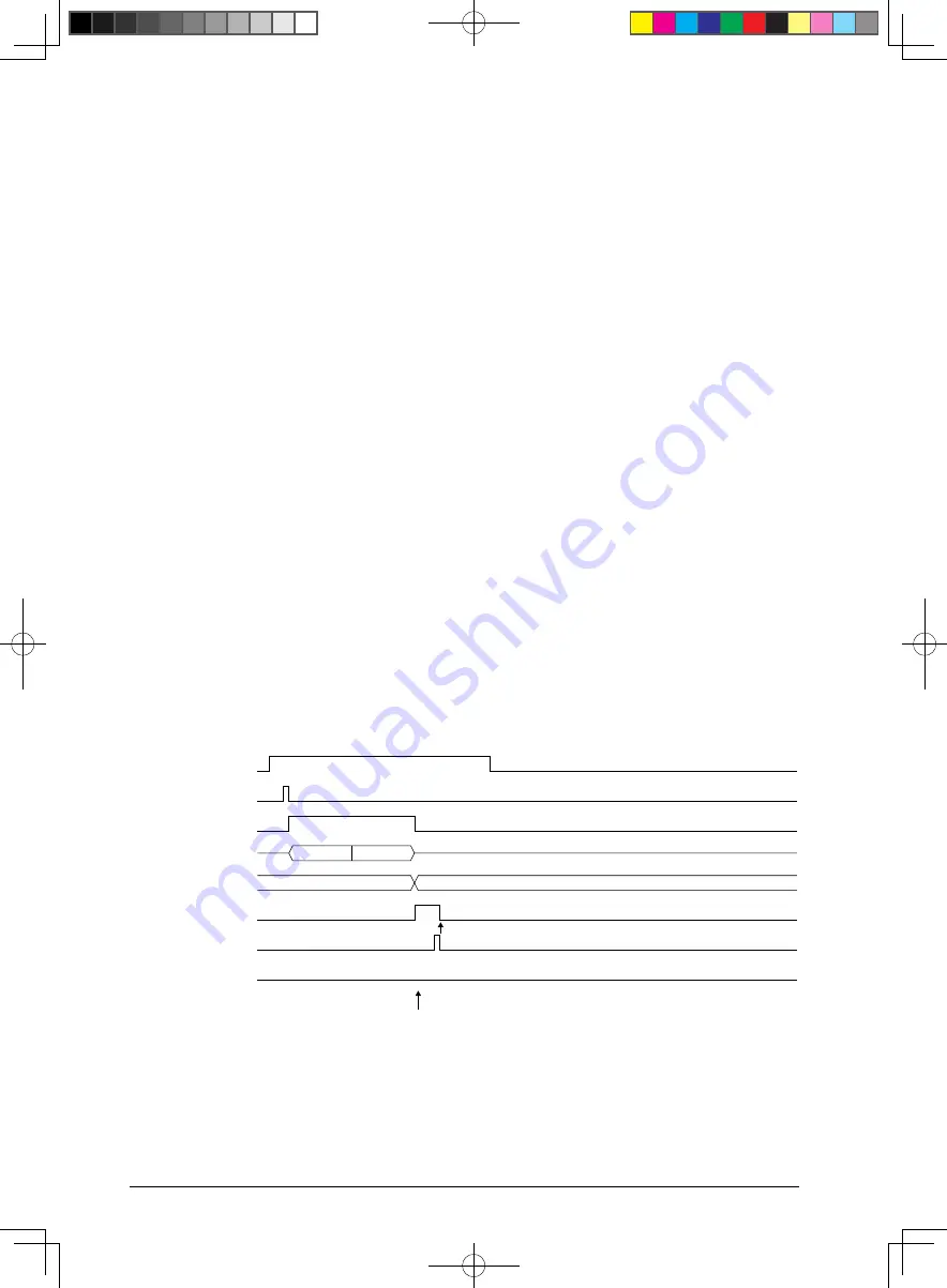
Figure 25.4.5.1 shows the operations of the A/D converter.
ADEN
Trigger
ADIBS
A/D operation
ADD[15:0]
ADCF
Conversion result read
ADOWE
Interrupt request
AIN0
Ch.0
AIN0
Sampling
Conversion
Clear
AIN0 converted data
(1) Single channel (AIN0) one-time conversion mode (ADCS = 0, ADCE = 0, ADMS = 0)


