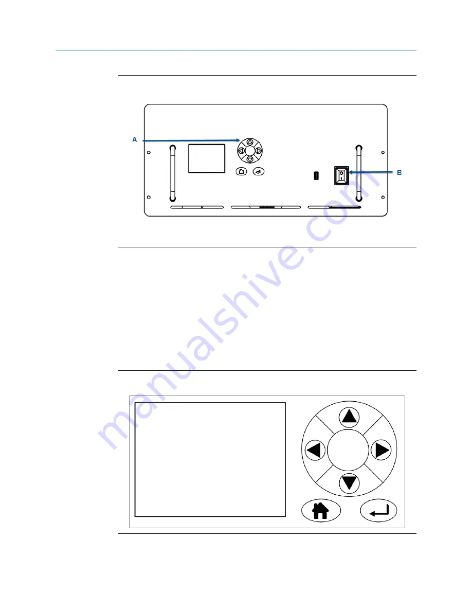
Front panel
Figure 4-3:
A.
Display controller
B.
Illuminated On/Off switch
The front panel On/Off switch (
Figure 4-3
, B) controls the application of electrical power to
the electronic circuits inside the instrument. On the switch, I identifies the
On
position and
O identifies the
Off
position. The switch includes an indicator that illuminates red when the
switch is set to
On
.
Note that setting the front panel On/Off switch to
Off
does
not
remove all electrical power
from the instrument. Part of the power distribution circuit will remain live. To remove all
electrical power from the instrument, set the On/Off switch on the rear panel (refer to
Section 4.4
) to
Off
.
Operation of the analyzer is controlled primarily through the display controller (
Figure 4-4
).
Display controller
Figure 4-4:
Operating the analyzer
Installation, Operations, and Maintenance Manual
27
Summary of Contents for Rosemount CT5400
Page 15: ...Abbreviation Description WEEE Waste electrical and electronic equipment μm Micro meter ...
Page 16: ......
Page 20: ...Contents iv Rosemount CT5400 ...
Page 32: ...Plan 12 Rosemount CT5400 ...
Page 40: ...Install 20 Rosemount CT5400 ...
Page 44: ...Startup procedure 24 Rosemount CT5400 ...
Page 54: ...Operating the analyzer 34 Rosemount CT5400 ...
Page 158: ...Troubleshooting and diagnostics 138 Rosemount CT5400 ...
Page 164: ...Shutdown procedure 144 Rosemount CT5400 ...
Page 166: ...Preventative maintenance 146 Rosemount CT5400 ...


