Screen overview
For more information visit:
www.EatonElectrical.com
MN05013005E
299
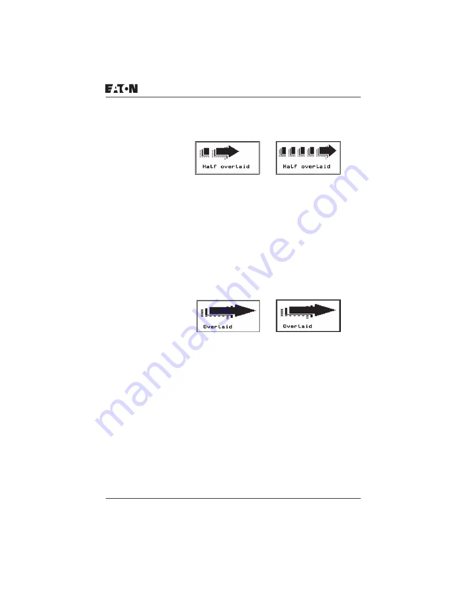
Figure 157: Overlaid bitmaps
Screen 2:
The second screen contains five overlaid bitmaps with each
subsequent bitmap being larger than the previous one
displayed. The individual bitmaps are made visible in
succession via the outputs Q1 to Q4 and the marker M01
(break contact bit logic). The Covered option is selected in the
Background area of the Display tab, therefore causing the
overlaid part of the bitmap to be covered by the bitmap in front
of it. In this way it is possible to create the impression of a
moving and expanding arrow.
Figure 158: “Expanding” arrow
Screen 3:
The third screen contains five fully overlaid bitmaps. These
are made invisible in succession from the top to the bottom via
the outputs Q1 to Q4 and the LED 3 (make contact bit logic).
The Covered option is selected in the Background area of the
Display tab. The overlaid section of the bitmap is therefore not
visible.
The first bitmap at the lowest level is permanently activated,
making it visible as long as all other bitmaps are invisible. This
produces a small moving picture.


