Screen overview
For more information visit:
www.EatonElectrical.com
MN05013005E
297
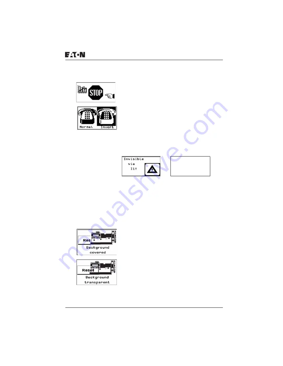
Screen 3:
Screen 3 contains three bitmaps that are arranged in different
sizes next to each other.
Screen 4:
Screen 4 contains two bitmaps that are arranged in different
sizes next to each other. The Invert Bitmap Display check box
activates the inverted display.
Screen 5:
Screen 5 contains one bitmap. The Visibility tab controls the
bitmap. I1 is used to make the bitmap invisible.
Figure 156: Switch invisible function
Screen 6:
Screen 6 contains only one bitmap. The Invert Bitmap Display
check box is activated in the Display tab. In the Visibility tab
the associated variable I2 is defined for switching visibility
(break contact bit logic). When I2 is actuated, the bitmap is
inverted as shown below.
Screen 7:
Screen 7 contains two bitmaps. Background covered is
selected in the Display tab for both bitmaps. However, as the
right bitmap covers the left one, the right bitmap is displayed
completely.
Screen 8:
Screen 8 contains two bitmaps. The right one covers the left
one. Both bitmaps are displayed fully since the background of
the right bitmap is set for transparent in the Display tab.
Invisible
via
I1!


