Instructional Literature
Page
134
Effective: May 2008
Instructions for the FP-6000 Protective Relay
For more information visit: www.eaton.com
IB02602004E
Standard Communication Board TB3
There are three circuits on the “Standard communication”
Terminal Block assembly TB3:
•
J1 INCOM PN – is the connection of a PowerNet INCOM
twisted pair communications interface. The connection is part
of a daisy chained multi-point twisted pair interface. J1-1 and
J1-2 are for the twisted pair connections and J1-3 for shield
termination. The removable terminal plug can facilitate debug
of the INCOM hardware interface. Switch selectable
termination is located on the communication board of the
inner chassis and can be accessed through an opening in the
metal chassis with the drawout removed. It is shipped open.
Refer to Section 10 for INCOM wiring rules and details.
•
J2 INCOM AB – this is an INCOM type interface reserved for
future design features. The hardware is identical to J1 accept
that there is a non-switch selectable 100 ohm termination
resistor built in.
•
J3 Zone Interlock – This is the termination for both the zone
interlock Zone Out (J3-1) and Zone In (J3-4) circuits with
duplicate J3-2 and J3-5 Zone com. connections, for Zone signal
returns. The shield connection J3-3 is grounded to the chassis
and is not needed for noise immunity. Twisted pair control
wiring of 14-18 AWG is recommended.
•
J4 and J5 are un-populated future design options.
•
J7 is the fiber optic port to communicate with URTD.
It is recommended that the wires terminated at TB3 be fitted on
the end with ferrules to eliminate fray shorting and the cable
stress released by strapping them to the back of the drawout
panel near the FP-6000.
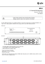
Figure 30. FP-6000 Outer Chassis Rear Connections.
1
2
3
4
5
6
7
8
9
10
1
TB1
2
TB2
3
TB3
4
J1
5
J2
6
J3
7
J4
8
J5
9
CT Receptical
Protective Earth
Fiber Optic Port
11