


91
Chapter 7: Preset Programming
PRESET PROGRAMMING
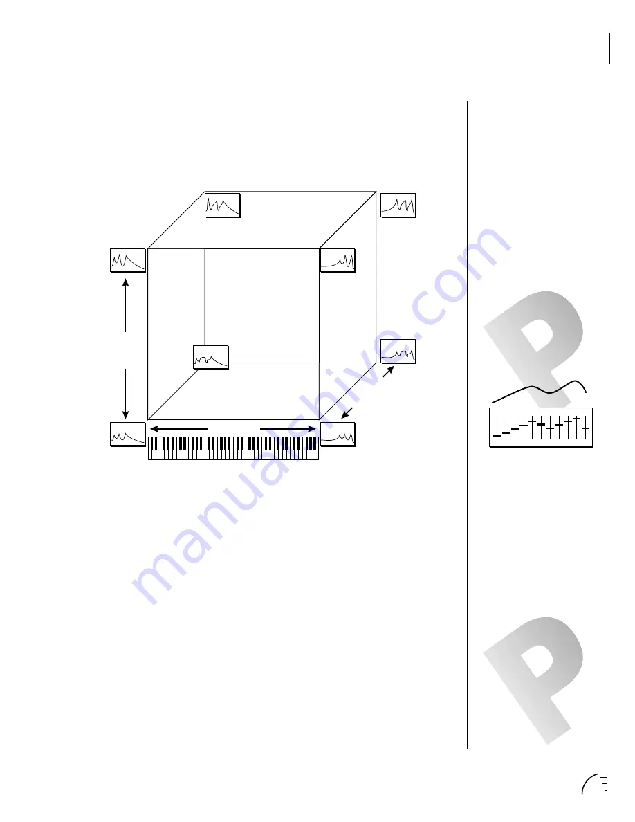
Suppose we added yet another dimension to the filter model. We could have the
realtime Morph parameter, the Frequency Tracking parameter (set at note-on
time) and one more parameter, perhaps controlling the amount of the filter
peaks with key velocity. One way to visualize a three-dimensional filter model is
shown by the diagram below.
NOTE: THE FREQUENCY
TRACKING PARAMETER IS
TRANSFORM 1.
Each axis of the three-dimensional cube changes the filter in a different way. In
the example above, key number is being applied to the Frequency Tracking
parameter in order to make the filter frequency track or follow the notes played
on the keyboard. Assigning the keyboard to frequency is called
Key Tracking
and is used to keep the timbre of the sound constant as you play up and down
the keyboard. Without key tracking the sound would get duller as you move up
the keyboard and could sound completely different at opposite ends of the
keyboard. Because Frequency Tracking is so important it has been assigned its
own parameter which is used in many of the filters (there are exceptions).
In the filter model above, there is another note-on (defined at the time the note
is pressed) parameter,
Transform 2
. Unlike the Frequency Tracking parameter,
the effect of Transform 2 may vary from filter to filter. In the example above,
Transform 2 is being used to vary the size of the peaks and notches in the filter.
The frequency plots in the upper plane of the cube have sharper peaks. Key
velocity could be used to control Transform 2 and the sharpness of the filter
peaks.
The
Cube
filters are actually constructed of eight different complex filters.
Key Number
Frequency Tracking
Transform 2
Velocity
Morph
Morph
Transform 2
Transform 2
Morph
Transform 2
Real-Time
Morph
Frequency Tracking
Frequency Tracking
Frequency Tracking
IF THE FREQUENCY GRAPHS AT
THE CORNERS OF THE CUBE ARE
CONFUSING YOU, THINK OF
THEM AS THE SETTINGS ON A
GRAPHIC EQUALIZER.
Summary of Contents for Ultraproteus
Page 1: ......
Page 11: ...Chapter 1 Basic Setup 1 UltraProteus INTRO BASIC SETUP ...
Page 12: ...UltraProteus Operation Manual 2 ...
Page 20: ...UltraProteus Operation Manual 10 ...
Page 21: ...11 Chapter 2 Basic Operation UltraProteus BASIC OPERATION ...
Page 27: ...27 Chapter 4 Midimap Menu UltraProteus MIDIMAP MENU ...
Page 28: ...28 UltraProteus Operation Manual ...
Page 37: ...37 Chapter 5 Effects Section UltraProteus EFFECTS SECTION ...
Page 38: ...38 UltraProteus Operation Manual ...
Page 57: ...37 Chapter 5 Effects Section UltraProteus EFFECTS SECTION ...
Page 58: ...38 UltraProteus Operation Manual ...
Page 77: ...57 Chapter 6 Hyperpreset Menu UltraProteus HYPERPRESET MENU ...
Page 78: ...58 UltraProteus Operation Manual ...
Page 87: ...83 Chapter 7 Preset Programming PRESET PROGRAMMING ...
Page 103: ...67 Chapter 7 Preset Programming PRESET PROGRAMMING UltraProteus PRESET PROGRAMMING ...
Page 104: ...68 UltraProteus Operation Manual PRESET PROGRAMMING ...
Page 120: ...99 Chapter 8 Preset Menu UltraProteus PRESET MENU ...
Page 121: ...100 UltraProteus Operation Manual ...
Page 149: ...128 UltraProteus Operation Manual ...
Page 150: ...129 Chapter 9 Copy Menu COPY MENU UltraProteus COPY MENU ...
Page 151: ...130 UltraProteus Operation Manual COPY MENU ...
Page 158: ...137 Chapter 10 Step by Step STEP BY STEP UltraProteus STEP BY STEP ...
Page 159: ...138 UltraProteus Operation Manual STEP BY STEP ...


