52
x
Platemaking / Master Feed / Ejection Section
chap.2
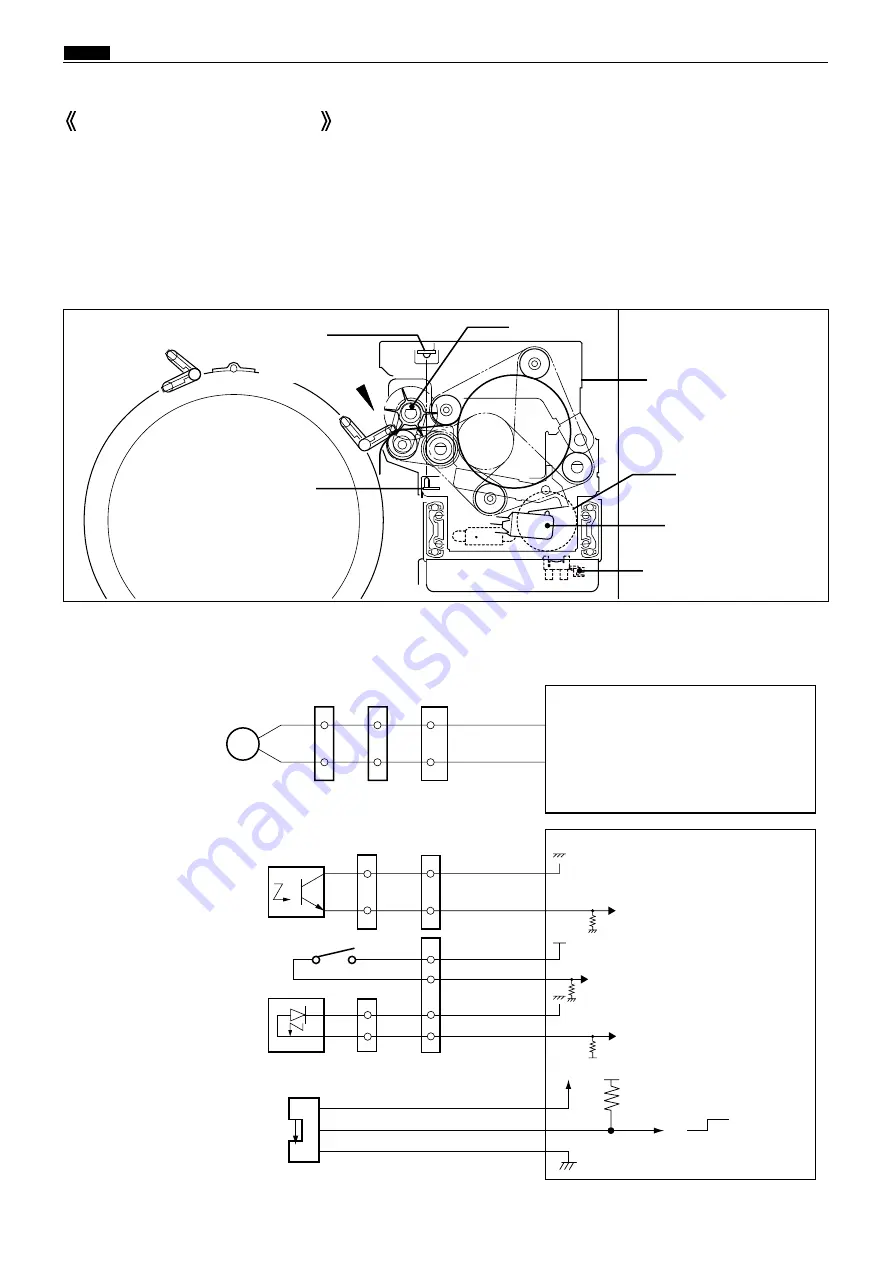
When the drum stops at the plate detachment position and the master clamp which clamps the master tip end
is opened (C mode), the pulling roller on the rolling section of the master ejection box pulls the master tip end
into the box inside, and the master is rolled up to the core.
If no core is installed, or when the master is fully wound onto the core, the ejection box full switch (MS8) is
mechanically actuated, and the message
"CHANGE MASTER EJECTION CORE"
appears on the LCD panel.
Blue
Blue
Brown
Black
7
8
1
2
Eject motor (Roll-up motor)
Ejection box sensor
Master ejection sensor
photo-emitting PCB
Ejection box full switch
Master ejection sensor
photo-receiving PCB
Gray
Pink
Blue
Yellow
Orange
Orange
3
4
1
2
5
6
M
CN9-24
-25
-20
-21
-1
-2
-22
-23
Drive PCB unit
Main PCB unit
5V
5V
5V
1
2
1
2
16
17
Red
Blue
CN20-4
1
2
3
-6
Pink
-5
5V
5V
5V
0
Photopassing :0V
Photointerrupting:5V
2. Circuit
1. Description
Master Ejection Section
Pulling roller
Master detachment
position
Master ejection sensor
photo-emitting PCB
Ejection box sensor
Ejection box full
switch
Eject motor
(Roll up motor)
Master ejection sensor
photo-receiving PCB
440318
440W13e
Master ejection unit
Summary of Contents for Duprinter DP-330
Page 9: ......
Page 11: ......
Page 18: ...c Dimensions chap 1 17 MEMO...
Page 24: ...4 8 2A 2B 2C 44000A1e b Part Names and Their Functions chap 1 23...
Page 152: ...151 MEMO...
Page 193: ...192 MEMO...
Page 329: ...328 x Overall Wiring Layout chap 8 15 Overall Wiring Layout 2 Drive PCB 2 2...


