204
z
Troubleshooting Guide
chap.6
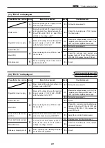
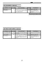
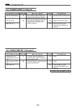
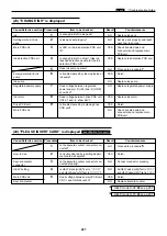
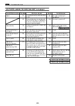
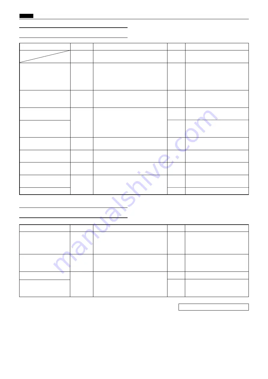
(17) "PLATE EJECTION ERROR" is displayed
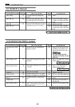
(18) Malfunction of Eject(Roll-up) Motor
Cause/Defective section Procedures
Item to be checked
Result
Countermeasure
1
YES
Proceed to procedure
5
.
Foreign material or dirt on
2
YES
Remove any foreign matter and
sensors.
clean.
Master ejection sensor
3
YES
Finish.
photo-receiving
Master ejection sensor
4
YES
Finish.
photo-emitting PCB
Main PCB unit
NO
Check bundled wire and
connectors and replace main
PCB unit.
Eject (Roll-up) motor
5
NO
Refer to “(18) Malfunction of eject
(roll-up) motor”.
Master clamp dirty.
6
YES
Clean master clamp section.
Master ejection box
7
YES
Replace any damaged stripper
finger or springs.
Drum master eject
8
NO
Adjust the drum master eject
stop position
stop position.
C mode
YES
Check and adjust C mode.
Has “PLATE EJECTION ERROR”
actually occurred?
Are there any foreign matter or dirt
between the master ejection sensor
photo-receiving and the master ejec-
tion sensor photo-emitting PCB?
Is trouble cleared by replacing the
master ejection sensor photo-receiv-
ing ?
Is trouble cleared by replacing the
master ejection sensor photo-emitting
PCB?
Does eject motor rotate normally?
Is the master clamp section dirty with
ink or oil?
Is stripper finger or springs damaged?
Is the drum master eject stop position
within reference value?
Cause/Defective section Procedures
Item to be checked
Result
Countermeasure
Eject (Roll-up) motor
1
YES
Replace Eject (Roll-up) motor .
Regulated power supply
2
NO
Replace regulated power supply.
Drive PCB unit
3
YES
Finish.
Main PCB unit
NO
Check bundled wire and
connectors and replace main
PCB unit.
Does voltage between drive PCB unit
CN9-24 (+) and -25 (GND) show 24V
when eject motor is operated with
HELP mode (H-02)
*
?
Does voltage between regulated
power S (+24) and -S (GND)
show 24V?
Is trouble cleared by replacing drive
PCB unit?
HELP mode H-02
\
see p.227
*
Summary of Contents for Duprinter DP-330
Page 9: ......
Page 11: ......
Page 18: ...c Dimensions chap 1 17 MEMO...
Page 24: ...4 8 2A 2B 2C 44000A1e b Part Names and Their Functions chap 1 23...
Page 152: ...151 MEMO...
Page 193: ...192 MEMO...
Page 329: ...328 x Overall Wiring Layout chap 8 15 Overall Wiring Layout 2 Drive PCB 2 2...


