167
c
Paper Feed Section
chap.4
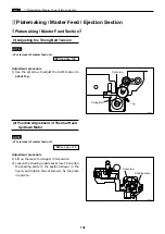
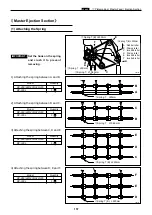
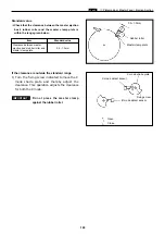
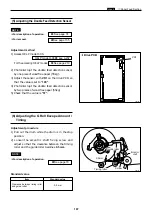
(6) Adjusting the G Roll Escape Amount /
Timing
Adjustment procedure
1) Pull out the drum while the drum is in the stop
position.
2) Loosen the eccentric shaft fixing screw and
adjust so that the clearance between the timing
roller and the guide roller becomes
0.5 mm
.
¡
For description of operation.
\
See page 70
NOTE :
Standard value
Item
Clearance between timing roller
and guide roller
0.5 mm
440121
0.5mm
Eccentric
shaft
Screw
Timing roller
Guide roller
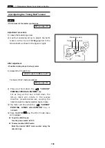
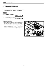
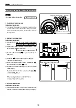
(5) Adjusting the Double Feed Detection Sensor
¡
For description of operation.
¡
For removal.
Adjustment method
1) Access HELP mode H-06.
For the accessing HELP modes:
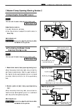
2) Photointerrupt the double feed detection sensor
by one piece of wood free paper (55kg).
3) Adjust the sensor with
VR1
on the drive PCB so
that the value is set to
“105”
.
4) Photointerrupt the double feed detection sensor
by two pieces of wood free paper (55kg).
5) Check that the value is
“57”
.
\
See page 219
HELP mode H-06
\
see p.232
\
See page 135
\
See page 74
NOTE :
440163
VR1
¡
Drive PCB
Standard value
Summary of Contents for Duprinter DP-330
Page 9: ......
Page 11: ......
Page 18: ...c Dimensions chap 1 17 MEMO...
Page 24: ...4 8 2A 2B 2C 44000A1e b Part Names and Their Functions chap 1 23...
Page 152: ...151 MEMO...
Page 193: ...192 MEMO...
Page 329: ...328 x Overall Wiring Layout chap 8 15 Overall Wiring Layout 2 Drive PCB 2 2...

