116
z
Exterior
chap.3
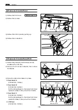
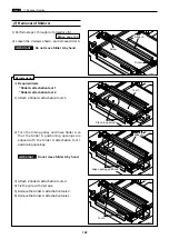
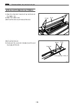
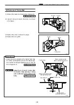
1) Remove the preciously mentioned (2) and (6).
and detach the LCD code.
2) Remove the 10 screws indicated, then remove
the bracket.
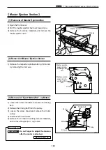
(7) Removal of Control Panel PCB
440107
Screws
Screws
Bracket
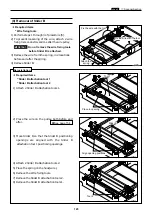
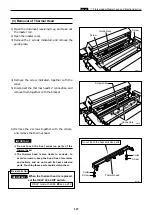
1) Remove the front cover.
\
See page 112
(6) Removal of Control Panel
3) Remove the control panel by pulling up.
4) Remove the 2 connectors.
440040
2) Remove the 4 screws.
Screw
Control panel
Screw
440106
Control panel
Connector
Connector
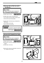
440108
Screws
Screws
Connector
Panel board C
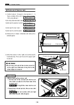
3) Follow the instructions below to remove.
¡
Panel board A
(2 connectors, 7 screws)
¡
Panel board B
(2 connectors, 6 screws)
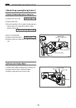
Pull the sliding stopper on the connector terminal
upwards to release it, then pull out the LCD cable.
¡
Panel board C
(2 connectors, 6 screws)
Pull the sliding stopper on the connector terminal
upwards to release it, then pull out the LCD cable.
¡
LCD Panel
(2 connectors, 4 screws)
Screws
Screws
Panel board B
Panel board A
LCD panel
Connector
Connector
Screws
Screws
Screws
Screws
Screw
Sliding stopper
Screws
q
Pull
upwards
w
Pull out
Screws
Summary of Contents for Duprinter DP-330
Page 9: ......
Page 11: ......
Page 18: ...c Dimensions chap 1 17 MEMO...
Page 24: ...4 8 2A 2B 2C 44000A1e b Part Names and Their Functions chap 1 23...
Page 152: ...151 MEMO...
Page 193: ...192 MEMO...
Page 329: ...328 x Overall Wiring Layout chap 8 15 Overall Wiring Layout 2 Drive PCB 2 2...


