29
2
c
Paper Feed Section .....................................................66
1. Description...............................................................66
2. Operation .................................................................67
(1) Rotation of the Paper Feed Roller and
Timing Roller .....................................................67
(2) Paper Feed Roller Drive.....................................68
(3) Driving of the Timing Roller..............................69
(4) Escape the Guide Roller.....................................70
(5) Paper Feed Length .............................................71
3. Function of Parts .....................................................72
(1) Printing Position Adjustment Mechanism .......72
(2) Double Feed Detect Mechanism ........................74
(3) Elevator Top Limit Sensor .................................75
(4) Elevator Lower Limit Switch ............................76
(5) Paper Sensor.......................................................77
(6) Elavator Encoder Sensor ..................................78
(7) Long Paper Unit Mechanism( Option ) ............78
v
Drum Driving Section ..................................................79
1. Description...............................................................79
2. Function of Parts ....................................................80
(1) Drum Stop / JAM Detect Position Sensor.........80
(2) Master Attach / Detach Position Sensor ...........81
(3) JOG Switch 1,2(Drum Rotation Switch 1,2).....82
(4) Control of the Main Motor .................................83
1. Rotation Speed Control by Encoder Sensor ...84
2. Selecting the Speed..........................................84
b
Press Section ...............................................................85
1. Description...............................................................85
(1) Press Roller Timing & Printing Area................85
2. Function of Parts ....................................................87
(1) P-Roll Sensor ......................................................87
(2) Switching the Contact Pressure ........................88
1. Contact pressure position sensing ..................89
n
Paper Ejection Section ................................................90
1. Description...............................................................90
2. Function of Parts ....................................................91
(1) Paper Stripper Finger ........................................91
(2) Top Blow Fan ......................................................92
(3) Paper Ejection Jam Sensor ...............................93
1. Paper JAM Detection Timing .........................94
(4) Paper Ejection Belt ............................................95
1. Paper ejection belt speed.................................95
(5) Paper aligning mechanism ................................96
m
Drum Section ...............................................................97
1. Description...............................................................97
2. Circuit .......................................................................98
3. Function of Part .......................................................99
(1) Ink Detection ......................................................99
1. LED Display and Output Signal on
the Ink Detection PCB Unit..........................100
2. "CHANGE INK" Display Timing ..................101
(2) Ink Roller Up / Down Mechanism ...................102
(3) Ink Pump ..........................................................104
(4) Drum Switch.....................................................105
(5) Fine Start Mode................................................106
(6) Drum Shift Mechanism....................................107
(7) Front Cover Detection Switch .........................108
,
Option .........................................................................109
(1) TAPE CLUSTER ..............................................109
Summary of Contents for Duprinter DP-330
Page 9: ......
Page 11: ......
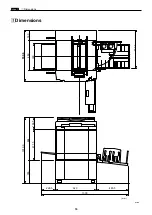
Page 18: ...c Dimensions chap 1 17 MEMO...
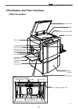
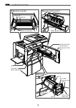
Page 24: ...4 8 2A 2B 2C 44000A1e b Part Names and Their Functions chap 1 23...
Page 152: ...151 MEMO...
Page 193: ...192 MEMO...
Page 329: ...328 x Overall Wiring Layout chap 8 15 Overall Wiring Layout 2 Drive PCB 2 2...


