212
x
Error Display
chap.6
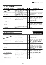
This machine has a self-diagnosis function. The state of the machine is always checked with this function and
is displayed with code on the control panel. The following are the code display, cause and detection timing.
Code display
Cause
Detectiontiming
E001
2
The main motor is defective.
2
The main motor PCB unit is defective.
2
The main PCB unit is defective.
2
The main motor encoder sensor is defective.
2
The regulated power supply is defective.
While the drum rotation signal is lit,the encorder sensor
cannnot detect the edge for 1 second.
E002
2
The elevator motor is defective.
2
The elevator top limit sensor is defective.
2
The elevator lower limit SW is defective.
2
The drive PCB unit is defective.
2
The main PCB unit is defective.
2
The elevator operation is defective.
2
The regulated power supply is defective.
The elevator dose not reach the top limit for 2 seconds after
the elevator up signal is lit.
The elevator dose not reach the lower limit for 2 seconds
after the elevator down signal is lit.
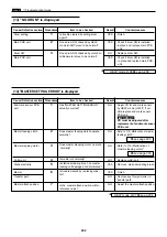
E005
2
The ink roller up/down motor is defective.
2
The regulated power supply is defective.
2
The drive PCB unit is defective.
2
The main PCB unit is defective.
2
The ink roller up/down sensor is defective.
While the ink roller up/down motor driving signal is lit,
the ink roller up/down sensor cannnot detect the edge
for 15 seconds.
E006
2
The pressure motor is defective.
2
The regulated power supply is defective.
2
The drive PCB unit is defective.
2
The main PCB unit is defective.
2
The pressure encoder sensor is defective.
While the pressure motor driving signal is lit,the pressure
encoder sensor cannnot detect the edge for 3 seconds.
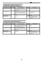
E008
2
The I/F PCB unit is defective.
2
The on-line csble is defective.
2
The I/F PCB B unit is defective.
2
The P-memory PCB unit is defective.
2
The main PCB unit is defective.
During on-line master-making,communication error occurs
between P-memory PCB unit and I/F PCB B unit.
During on-line master-making,communication error occurs
between main PCB unit and I/F PCB unit.
E011
2
The thermal head up/down motor is defective.
2
The regulated power supply is defective.
2
The drive PCB unit is defective.
2
The thermal head position sensor is defective.
2
The main PCB unit is defective.
While the thermal head up/down motor driving signal is lit,
the thermal head position sensor cannnot detect the edge
for 4 seconds.
E009
2
The thermal head is defective.
2
The regulated power supply is defective.
At start of master-making, thermal head drive voltage
dose not reach reguration value.
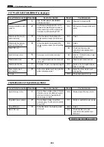
E013
2
The scanner stepping motor is defective.
2
The regulated power supply is defective.
2
The main PCB unit is defective.
2
The scanner home position sensor is defective.
2
The drive PCB unit is defective.
At master-making, while the scanner stepping motor driving
signal is lit,the scanner home position sensor cannnot detect
the edge for 17 seconds.
E014
2
The regulated power supply is defective.
2
The roller motor is defective.
2
The G roller sensor is defective.
2
The main PCB unit is defective.
2
The drive PCB unit is defective.
While the roller motor driving signal is lit,the G roller
sensor cannnot detect the edge for 2 seconds.
E015
2
The regulated power supply is defective.
2
The main PCB unit is defective.
2
The drive PCB unit is defective.
2
The top/bottom motor is defective.
2
The top/bottom encoder sensor is defective.
2
The top/bottom center sensor is defective.
While the top/bottom motor driving signal is lit,the top/bottom
encoder sensor cannnot detect the edge for 3 seconds.
E016
2
The regulated power supply is defective.
2
The main PCB unit is defective.
2
The drive PCB unit is defective.
2
The drum limit/center sensor is defective.
2
The sideways stepping motor is defective.
While the sideways stepping motor driving signal is lit,
the sensor cannnot detect the edge for 12 seconds.
x
Error Display
Summary of Contents for Duprinter DP-330
Page 9: ......
Page 11: ......
Page 18: ...c Dimensions chap 1 17 MEMO...
Page 24: ...4 8 2A 2B 2C 44000A1e b Part Names and Their Functions chap 1 23...
Page 152: ...151 MEMO...
Page 193: ...192 MEMO...
Page 329: ...328 x Overall Wiring Layout chap 8 15 Overall Wiring Layout 2 Drive PCB 2 2...


