142
n
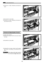
Paper Ejection Section
chap.3
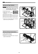
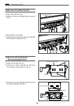
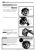
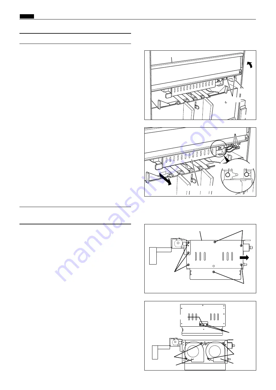
1) Open the top blow fan cover.
2) Remove the 2 screws indicated, then remove the
cover.
(6) Removal of Top Blow Fan Unit
440153
Screws
Cover
Top blow fan cover
440154
loosen
3) Disconnect the 3 connectors.
4) Loosen the screw and remove the screw indicated,
then remove the top blow fan unit.
remove
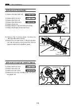
1) Remove the top blow fan unit.
2) Remove the 7 screws indicated, and remove the
cover sliding in the direction of an arrow.
(7) Removal of Fan/Jam Sensor
(Photo-emitting PCB Unit)
440155
Screws
Fan cover under unit
440156
Screws
Photo-emitting PCB
3) Remove the 2 screws indicated, then remove the
fan / photo-emitting PCB sensor.
Fan
Screws
Screws
Screws
Screws
Fan
Top blow fan unit
Connectors
Summary of Contents for Duprinter DP-330
Page 9: ......
Page 11: ......
Page 18: ...c Dimensions chap 1 17 MEMO...
Page 24: ...4 8 2A 2B 2C 44000A1e b Part Names and Their Functions chap 1 23...
Page 152: ...151 MEMO...
Page 193: ...192 MEMO...
Page 329: ...328 x Overall Wiring Layout chap 8 15 Overall Wiring Layout 2 Drive PCB 2 2...


