195
z
Troubleshooting Guide
chap.6
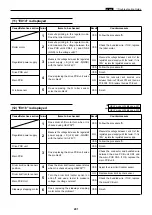
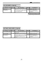
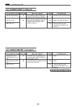
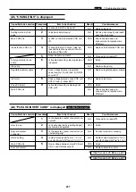
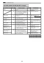
(1) Lamp does not Light Up
Cause/Detective section Procedures
Result
Countermeasure
Items to be checked
Regulated power supply
1
Measure the voltage between the regulated
power supply, +S (+24) and -S(GND)
with the tester. Is it +24V?
NO
Measure the voltage between L and N of the
regulated power supply with the tester. If it is
100V, replace the regulated power supply.
Drive PCB Unit
2
Measure the drive PCB unit CN5-1 (+)
and CN5-3(GND) with the tester. Is it
+24V?
NO
Replace the drive PCB Unit.
3
Does the lamp light up when the drive
PCB unit CN9-9 produces a short cir-
cuit to GND?
YES
Follow the procedure
5
.
Drive PCB Unit
4
Is the cause cleared by replacing the
drive PCB Unit?
YES
Finish.
Main PCB Unit
NO
Replace the main PCB Unit.
Lamp
5
Is the cause cleared by replacing the
lamp?
YES
Finish.
Inverter PCB Unit
NO
Replace the inverter PCB Unit.
Thermal head
6
Is the cause cleared by replacing the
thermal head?
YES
Finish.
Thermal head PCB Unit
NO
Replace the thermal head PCB Unit.
Motors
7
Remove the drive PCB Unit CN5 and
follow the procedure
1
.
Is the v24V? (CN1 is inserted)
YES
At the CN5 bundled wire or motors
+24V produces a short-circuit to GND.
Follow the procedure
2
.
YES
Summary of Contents for Duprinter DP-330
Page 9: ......
Page 11: ......
Page 18: ...c Dimensions chap 1 17 MEMO...
Page 24: ...4 8 2A 2B 2C 44000A1e b Part Names and Their Functions chap 1 23...
Page 152: ...151 MEMO...
Page 193: ...192 MEMO...
Page 329: ...328 x Overall Wiring Layout chap 8 15 Overall Wiring Layout 2 Drive PCB 2 2...


