143
n
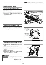
Paper Ejection Section
chap.3
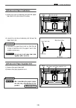
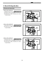
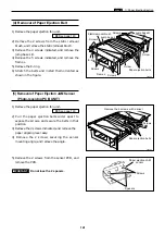
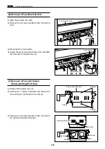
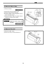
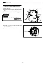
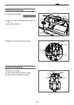
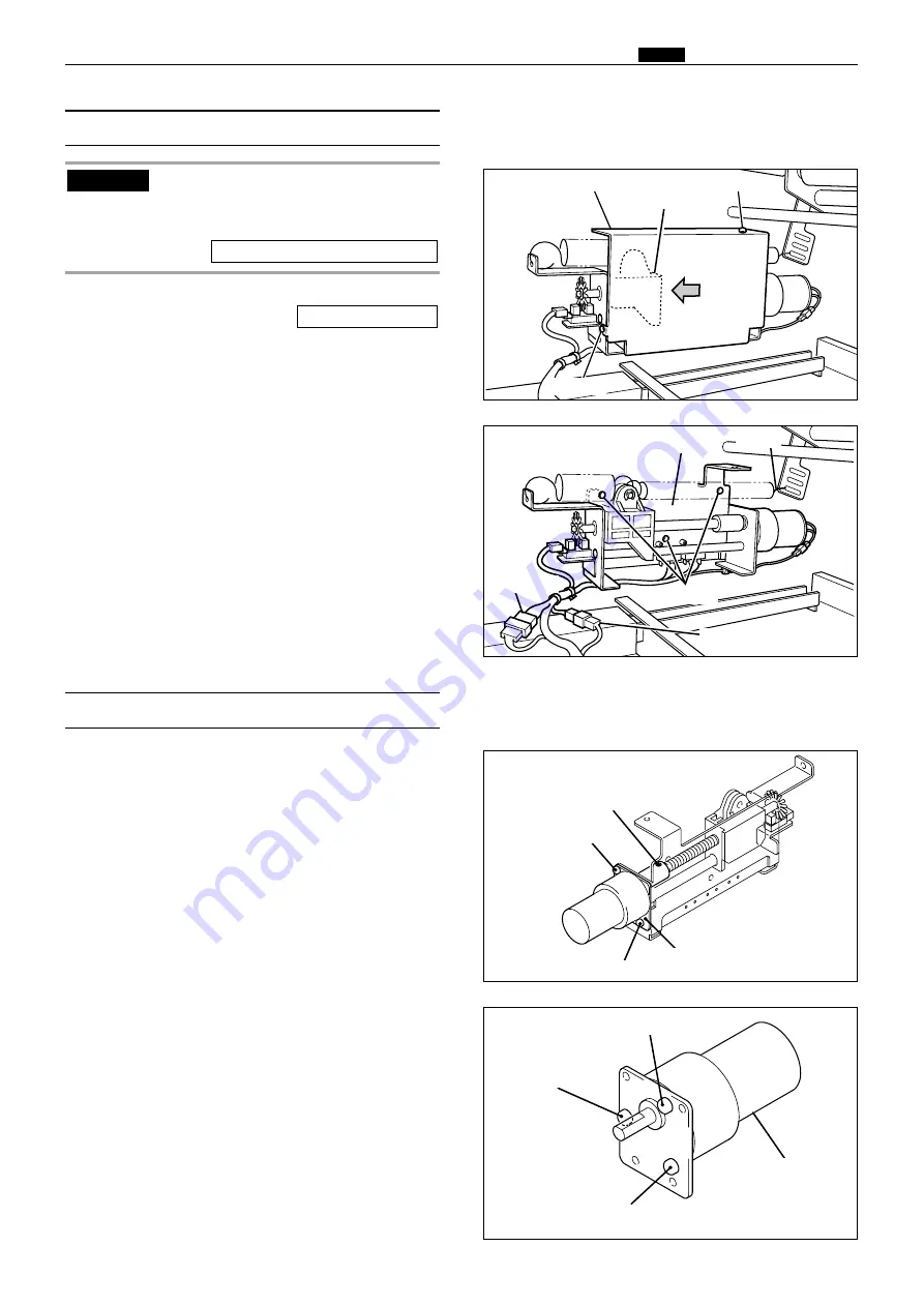
1) Remove the paper ejection fan unit.
2) Remove the 2 screws indicated, then remove the
cover.
\
See page 140
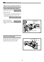
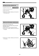
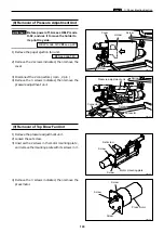
(8) Removal of Pressure Adjustment Unit
440157
Cover
440158
Screws
Pressure adjustment unit
Connector
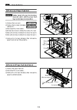
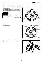
3) Disconnect the 2 connectors.( 4 pin , 2 pin )
4) Remove the 3 screws indicated, then remove the
pressure adjustment unit.
Screw
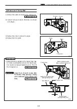
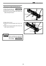
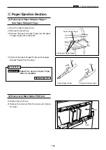
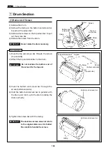
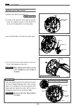
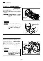
1) Remove the pressure adjustment unit.
2) Loosen the set screw.
3) Unscrew the 2 screws in the motor mounting plate ,
and remove the mounting plate with its screws in it.
(9) Removal of Top Blow Fan Unit
440159
440160
Press motor
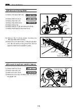
4) Remove the 3 screws indicated, then remove the
press motor.
Screw
Screw
Screw
Screw
Screw
Set screw
Motor mounting plate
Connector
Screw
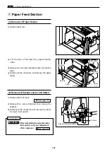
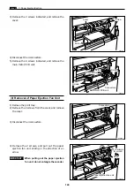
Before power off, Access HELP mode
H-02, and use it to move the holder to
its print tray side.
HELP mode H-02
\
see p.227
IMPORTANT :
Holder
Spring
Summary of Contents for Duprinter DP-330
Page 9: ......
Page 11: ......
Page 18: ...c Dimensions chap 1 17 MEMO...
Page 24: ...4 8 2A 2B 2C 44000A1e b Part Names and Their Functions chap 1 23...
Page 152: ...151 MEMO...
Page 193: ...192 MEMO...
Page 329: ...328 x Overall Wiring Layout chap 8 15 Overall Wiring Layout 2 Drive PCB 2 2...

