


Dell PowerConnect 55xx Systems User Guide
89
FILE LOCATION: C:\Users\gina\Desktop\Checkout_new\Maintenance Projects\Dell
Contax\sources\CxUGAdmin.fm
D E L L CO N F I D E N T I A L – P R E L I MI N A RY 10 / 3 0 /1 3 - FO R PR O O F O N LY
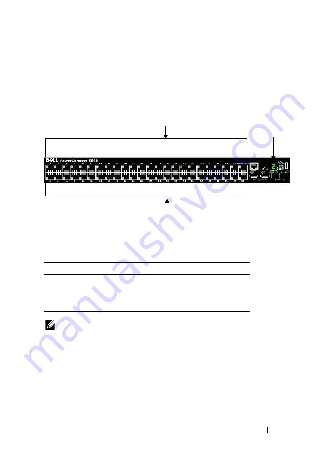
Device Representation
The home page contains a graphical representation of the units in the stack’s
front panels. Figure 7-1 displays the 5548 model, but the display for the other
models are similar.
Figure 7-1. PowerConnect Device Port Indicators
The graphic display on the home page displays the Unit ID and port
indicators that specify whether a specific port is currently active. Table 7-1
describes the port colors that are displayed and their meaning:
Table 7-1. Port Colors
NOTE:
For more information about LEDs, see "LED Definitions" on page 40.
To configure a port double-click on its icon.
Only ports that are physically present are displayed in the PowerConnect
OpenManage Switch Administrator home page, and can be configured
through the web management system. Non-present ports can be configured
through the CLI or SNMP interfaces.
Port Representation
Ports are referred to in the notation: [gi/te]x/0/z, where:
Component Description
Amber
The port is currently connected at 100 Mbps.
Green
The port is currently connected at 1000 Mbps
Grey
The port is currently disconnected
Stacking Unit ID
Giga Ports (odd numbered)
Giga Ports (even numbered)


