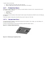
1
Screws (2)
2
Hinge retaining bar
3
Hinged door
To remove a hinged door:
NOTICE:
The number of screws and retaining bars will vary depending on the exact hinge
assembly.
1.
Follow the procedures in “Before You Begin”.
2.
Turn the computer bottom-side up, remove the screws that are securing the hinge retaining bar(s).
3.
Lift the hinge retaining bar(s) away from the computer.
4.
Slide the hinged door away from the system.
5.
Reverse the procedure to install a new hinged door.
14.7.3
Friction Fit Door
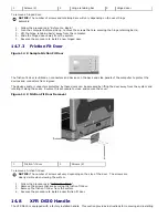
Figure 14 8 Sample Friction Fit Door
The friction fit door is utilized on connectors and devices on the back and side panels of the computer to protect the
devices and connectors from ingress.
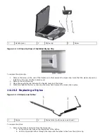
The devices and/or connectors protected by these doors can be accessed by lifting the door away from the system and
rotating it along the seam. Reverse this procedure to close and secure the cover.
Figure 14 9 Friction Fit Door Removal
1
Friction fit door
2
Screws (2)
To remove a friction fit door:
NOTICE:
The number of screws will vary depending on the size of the door. The screws are
clearly visible when viewing the system.
1.
Follow the procedures in “
308H
Before You Begin”.
2.
Remove the screws that are securing the friction fit door.
3.
Remove the friction fit door from the system.
4.
Reverse the procedure to install a new friction fit door.
14.8
XFR D630 Handle
The XFR D630 is equipped with a factory installed handle. This section provides instructions for removing and installing

