Diagnostic information
2-1
2. Diagnostic information
Start
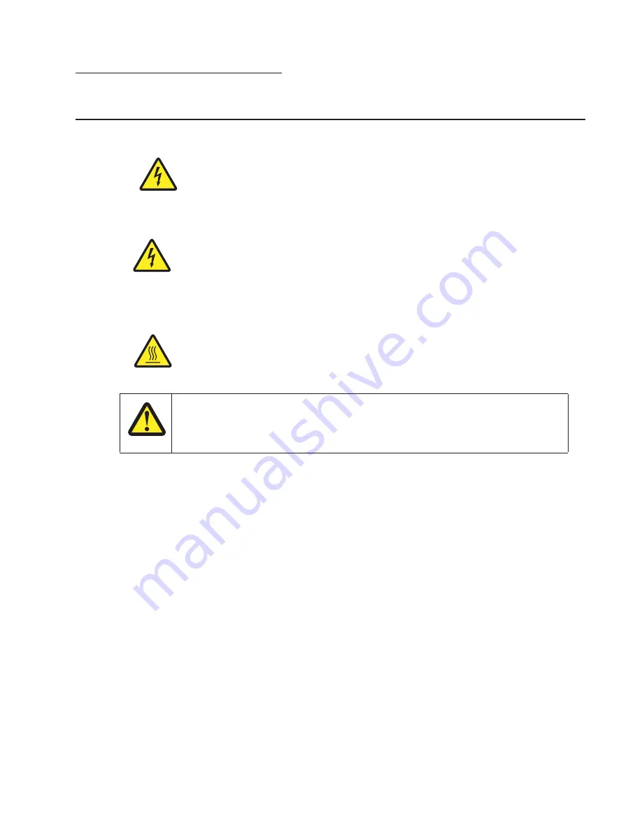
WARNING:
When operating the driving units using the diagnostics or other tools, be sure to keep them covered
unless otherwise specified.
WARNING:
When operating the driving units using the diagnostics or other tools, never touch the driving units.
When operating the driving units using diagnostics or other tools, be sure to follow the procedures in this
manual.
WARNING:
Servicers should wear a wrist band or the like to remove static electricity from their body, grounding
their body while working. Go to
“Handling ESD-sensitive parts” on page 4-1
.
Note:
There may be printer error messages that are not contained in this service manual. Call your next level
support for assistance.
CAUTION:
Unplug the power cord from the electrical outlet before you connect or disconnect any cable
electronic board or assembly.
CAUTION:
If the printer is kept on, never touch the conductive parts if not specifically required. The power
switch and inlet of the low voltage power supply card (LVPS card) assembly is live even while
the power supply is cut off. Never touch the live parts.
CAUTION:
Be careful to avoid burns by safely handling hot parts.
CAUTION
The printer weight is greater than 18kg (40 lbs) and requires two or more trained personnel to
lift it safely. Use the hand holds on the side of the printer. Make sure your fingers are not
under the printer when you lift or set the printer down.
Summary of Contents for 5230DN
Page 1: ... HOO Q GQ GQ GQ 6HUYLFH 0DQXDO 15 December 2009 ...
Page 2: ... ...
Page 14: ...xiv Service Manual ...
Page 19: ...Notices and safety information xix ...
Page 20: ...xx Service Manual ...
Page 34: ...1 10 Service Manual ...
Page 206: ...2 172 Service Manual ...
Page 318: ...3 112 Service Manual ...
Page 366: ...4 48 Service Manual 6 Remove the operator panel hinge assembly right ...
Page 369: ...Repair Information 4 51 9 Lift the operator panel door assembly out of the machine ...
Page 436: ...4 118 Service Manual 3 Remove the HCIT tray cover front A ...
Page 438: ...4 120 Service Manual 3 Remove the HCIT cover rear ...
Page 440: ...4 122 Service Manual 3 Remove the HCIT cover right ...
Page 469: ...Repair Information 4 151 5 Install the flash card into the system board ...
Page 518: ...4 200 Service Manual ...
Page 520: ...5 2 Service Manual ...
Page 524: ...7 2 Service Manual Assembly 1 Covers ...
Page 526: ...7 4 Service Manual Assembly 2 5230n dn 5350dn and 5530dn Operator panel ...
Page 528: ...7 6 Service Manual Assembly 3 T656dne Operator panel MPF and smart card ...
Page 530: ...7 8 Service Manual Assembly 4 Drive motor assemblies and duplex ...
Page 532: ...7 10 Service Manual Assembly 5 Media path and ducts 1 2 2 3 4 5 6 7 8 9 10 11 12 12 ...
Page 534: ...7 12 Service Manual Assembly 6 Printhead charge and transfer ...
Page 536: ...7 14 Service Manual Assembly 7 Pick arm assembly trays and MPF ...
Page 538: ...7 16 Service Manual Assembly 8 LVPS fuser and electrical cables 1 ...
Page 540: ...7 18 Service Manual Assembly 9 HVPS system card and electrical cables 2 ...
Page 548: ...7 26 Service Manual Assembly 13 SFP stapler assembly 1 1 ...
Page 552: ...7 30 Service Manual Assembly 15 SFP stapler assembly 3 4 5 1 2 3 6 6 7 8 9 10 11 ...
Page 554: ...7 32 Service Manual Assembly 16 SFP stapler assembly 4 1 2 ...
Page 556: ...7 34 Service Manual Assembly 17 5 bin mailbox 1 3 12 7 5 2 11 4 13 8 10 9 1 14 6 ...
Page 564: ...7 42 Service Manual Assembly 21 Envelope feeder and external duplex 1 2 ...
Page 582: ...I 12 Service Manual ...
Page 584: ...5230n dn Printer ...
Page 585: ...5 5 30dn Printer ...
Page 586: ...5 35 0dn Printer ...


