4-4
Service Manual
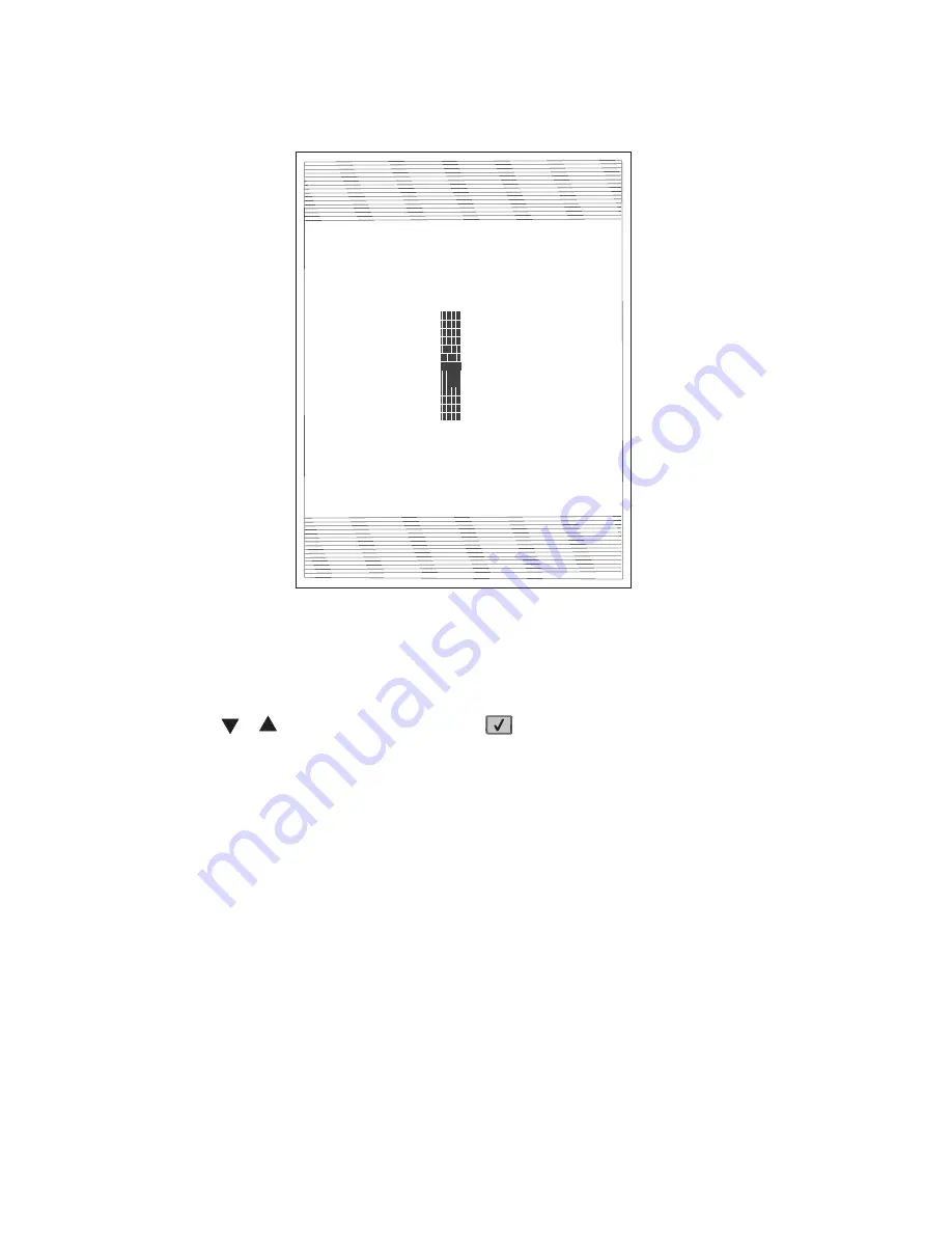
alignment printout is shown below:
6. In the Registration menu, select the right margin setting.
7. To determine the margin setting, choose the value that is closest to the darkest bar on the center graph of
the margin page. Add that value to the current right margin setting printed on the left hand side of the margin
page. (The right margin setting will also appear on the operator panel display.) For example, if the right
margin setting on the page is -2, and the number that is closest to the darkest line on the graph is 3
(-2+3), then the right margin setting will be equal to +1.
8. Press
or
to the desired setting, and press
.
9. Print the Quick Test page again and check that the darkest line in the center graph is equal to zero. If it is,
then check to see if the left, top, and bottom margins are detected. If it is not, then repeat step 5.
Note:
The alignment of the left margin positions the black plane to the right or left. The alignment of the right
margin does not alter the margins and should only be used to adjust the printhead.
Alignment assembly adjustment
Do the alignment assembly adjustment whenever you replace the alignment assembly. Always print a copy of
the Quick Test Page before making any adjustments to the alignment assembly reference adjustment screw.
When replacing the alignment assembly, it is necessary to back the reference adjustment screw out far enough
to remove the old assembly and install the new one.
•
If you are replacing the alignment assembly, go to step A.
•
If you are only adjusting the reference adjustment screw, go to step B.
Step A
Print a copy of the Quick Test Page and check the margin adjustments printed on the test page. These settings
should be within the range specified in
“Registration” on page 3-67
.
Do the reference adjustment if you are sure the margins are set correctly.
Loader
Kernel
Base
Network
Netwrk Drvr
Engine
Panel
Font
LF.LBH.P055-0
FFN.APS.F191a-0
LF.LBH.P055-0
NF.APS.N179-0
LF.LBH.P055-0
AF.LB.E037-0
9.9
8.31M02-U5.0
Quick Test
Device Information
Printer Revision Levels
Printer Margin Settings
Page Cou nt
Installed Memory
Processor Speed
31
192 MB
467MHz
Serial Number
0116413
TDS Calibration
00 14 FF 00 00 00 00
Engine ID
40
System Card ID
0004007E24A2
Top Margin
= 5
Bottom Margin
= 0
Left Margin
Right Margin
Dup Top Margin
Dup Left Margin
Paper Source
Formatted Size
= -3
= 0
= 0
= 0
= Tray 1
= Letter
Darkest bar indicates
ADJUSTMENT AMOUNT
for bidirectional alignment
- 12
- 10
- 8
- 6
- 4
- 2
0
+ 2
+ 4
+ 6
+ 8
+ 10
+ 12
Dell
Summary of Contents for 5230DN
Page 1: ... HOO Q GQ GQ GQ 6HUYLFH 0DQXDO 15 December 2009 ...
Page 2: ... ...
Page 14: ...xiv Service Manual ...
Page 19: ...Notices and safety information xix ...
Page 20: ...xx Service Manual ...
Page 34: ...1 10 Service Manual ...
Page 206: ...2 172 Service Manual ...
Page 318: ...3 112 Service Manual ...
Page 366: ...4 48 Service Manual 6 Remove the operator panel hinge assembly right ...
Page 369: ...Repair Information 4 51 9 Lift the operator panel door assembly out of the machine ...
Page 436: ...4 118 Service Manual 3 Remove the HCIT tray cover front A ...
Page 438: ...4 120 Service Manual 3 Remove the HCIT cover rear ...
Page 440: ...4 122 Service Manual 3 Remove the HCIT cover right ...
Page 469: ...Repair Information 4 151 5 Install the flash card into the system board ...
Page 518: ...4 200 Service Manual ...
Page 520: ...5 2 Service Manual ...
Page 524: ...7 2 Service Manual Assembly 1 Covers ...
Page 526: ...7 4 Service Manual Assembly 2 5230n dn 5350dn and 5530dn Operator panel ...
Page 528: ...7 6 Service Manual Assembly 3 T656dne Operator panel MPF and smart card ...
Page 530: ...7 8 Service Manual Assembly 4 Drive motor assemblies and duplex ...
Page 532: ...7 10 Service Manual Assembly 5 Media path and ducts 1 2 2 3 4 5 6 7 8 9 10 11 12 12 ...
Page 534: ...7 12 Service Manual Assembly 6 Printhead charge and transfer ...
Page 536: ...7 14 Service Manual Assembly 7 Pick arm assembly trays and MPF ...
Page 538: ...7 16 Service Manual Assembly 8 LVPS fuser and electrical cables 1 ...
Page 540: ...7 18 Service Manual Assembly 9 HVPS system card and electrical cables 2 ...
Page 548: ...7 26 Service Manual Assembly 13 SFP stapler assembly 1 1 ...
Page 552: ...7 30 Service Manual Assembly 15 SFP stapler assembly 3 4 5 1 2 3 6 6 7 8 9 10 11 ...
Page 554: ...7 32 Service Manual Assembly 16 SFP stapler assembly 4 1 2 ...
Page 556: ...7 34 Service Manual Assembly 17 5 bin mailbox 1 3 12 7 5 2 11 4 13 8 10 9 1 14 6 ...
Page 564: ...7 42 Service Manual Assembly 21 Envelope feeder and external duplex 1 2 ...
Page 582: ...I 12 Service Manual ...
Page 584: ...5230n dn Printer ...
Page 585: ...5 5 30dn Printer ...
Page 586: ...5 35 0dn Printer ...


