


Diagnostic aids
3-109
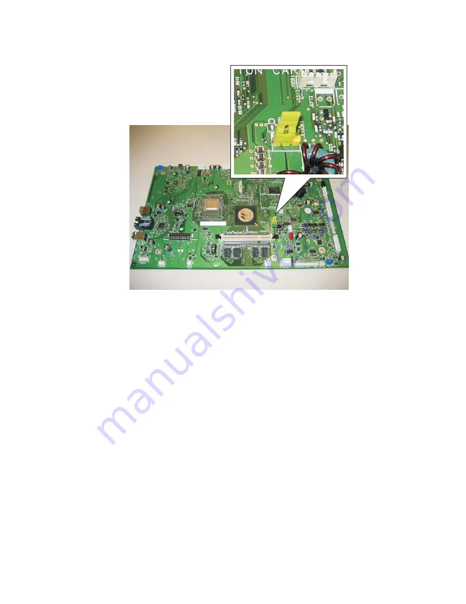
3.
Remove the small yellow jumper that covers a pair of the jumper’s pins.
4.
Replace the small yellow jumper so that it covers the pins adjacent to its original position.
5.
Replace and secure the Kensington lock on the card cage (if installed).
6.
Power the device on.
Note:
The movement of the small yellow jumper from position A to position B triggers the reset, not the
specific positions. When the device is powered on, it labels the current position of the small yellow jumper (let’s
say position A) as the “home ” position. If, at the next POR, the device detects that the small yellow jumper has
moved from its previous “home ” position (position A) to the “ other ” position (position B), then it performs a
jumper reset. After performing the reset, the device also relabels the “ other ” position (position B) as the “
home ” position (now position A is the “other ” location).
Note:
The admin's security settings are lost when the RIP card is replaced. Secure settings are those that are
configured under the Settings->Security->Edit Security Setups menu. These are all the PINs, Passwords, and
other Building Blocks and Security Templates that define the device's protection of functions and menus. In
other words, if the customer is using LDAP to authenticate users to use the Copy function, then after the RIP
card is replaced, the device will no longer have that LDAP configuration or the Copy function protected.
Top
Bottom
Rear
Front
Summary of Contents for 5230DN
Page 1: ... HOO Q GQ GQ GQ 6HUYLFH 0DQXDO 15 December 2009 ...
Page 2: ... ...
Page 14: ...xiv Service Manual ...
Page 19: ...Notices and safety information xix ...
Page 20: ...xx Service Manual ...
Page 34: ...1 10 Service Manual ...
Page 206: ...2 172 Service Manual ...
Page 318: ...3 112 Service Manual ...
Page 366: ...4 48 Service Manual 6 Remove the operator panel hinge assembly right ...
Page 369: ...Repair Information 4 51 9 Lift the operator panel door assembly out of the machine ...
Page 436: ...4 118 Service Manual 3 Remove the HCIT tray cover front A ...
Page 438: ...4 120 Service Manual 3 Remove the HCIT cover rear ...
Page 440: ...4 122 Service Manual 3 Remove the HCIT cover right ...
Page 469: ...Repair Information 4 151 5 Install the flash card into the system board ...
Page 518: ...4 200 Service Manual ...
Page 520: ...5 2 Service Manual ...
Page 524: ...7 2 Service Manual Assembly 1 Covers ...
Page 526: ...7 4 Service Manual Assembly 2 5230n dn 5350dn and 5530dn Operator panel ...
Page 528: ...7 6 Service Manual Assembly 3 T656dne Operator panel MPF and smart card ...
Page 530: ...7 8 Service Manual Assembly 4 Drive motor assemblies and duplex ...
Page 532: ...7 10 Service Manual Assembly 5 Media path and ducts 1 2 2 3 4 5 6 7 8 9 10 11 12 12 ...
Page 534: ...7 12 Service Manual Assembly 6 Printhead charge and transfer ...
Page 536: ...7 14 Service Manual Assembly 7 Pick arm assembly trays and MPF ...
Page 538: ...7 16 Service Manual Assembly 8 LVPS fuser and electrical cables 1 ...
Page 540: ...7 18 Service Manual Assembly 9 HVPS system card and electrical cables 2 ...
Page 548: ...7 26 Service Manual Assembly 13 SFP stapler assembly 1 1 ...
Page 552: ...7 30 Service Manual Assembly 15 SFP stapler assembly 3 4 5 1 2 3 6 6 7 8 9 10 11 ...
Page 554: ...7 32 Service Manual Assembly 16 SFP stapler assembly 4 1 2 ...
Page 556: ...7 34 Service Manual Assembly 17 5 bin mailbox 1 3 12 7 5 2 11 4 13 8 10 9 1 14 6 ...
Page 564: ...7 42 Service Manual Assembly 21 Envelope feeder and external duplex 1 2 ...
Page 582: ...I 12 Service Manual ...
Page 584: ...5230n dn Printer ...
Page 585: ...5 5 30dn Printer ...
Page 586: ...5 35 0dn Printer ...


