


3-96
Service Manual
Understanding jam numbers and locations
When a jam occurs, a message indicating the jam location appears. Open doors and covers and remove trays
to access jam locations. To resolve any paper jam message, you must clear all jammed paper from the paper
path.
The following table lists the jams that can occur and the location of each jam:
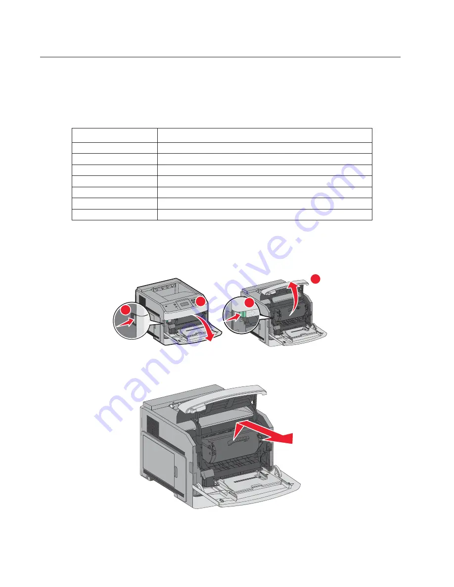
200 and 201 paper jams
1.
Push the release latch, and then lower the multipurpose feeder door.
2.
Push the release latch, and then open the front cover.
3.
Lift and pull the print cartridge out of the printer.
WARNING:
Do not touch the photoconductor drum on the underside of the cartridge. Use the cartridge handle
whenever you are holding the cartridge.
4.
Place the print cartridge aside on a flat, smooth surface.
Jam numbers
Area
200—203
Printer
230—239 Duplex
unit
241—245 Paper
trays
250 Multipurpose
feeder
260 Envelope
feeder
270—279
Optional output bins
28x
Stapler
3
4
1
2
Summary of Contents for 5230DN
Page 1: ... HOO Q GQ GQ GQ 6HUYLFH 0DQXDO 15 December 2009 ...
Page 2: ... ...
Page 14: ...xiv Service Manual ...
Page 19: ...Notices and safety information xix ...
Page 20: ...xx Service Manual ...
Page 34: ...1 10 Service Manual ...
Page 206: ...2 172 Service Manual ...
Page 318: ...3 112 Service Manual ...
Page 366: ...4 48 Service Manual 6 Remove the operator panel hinge assembly right ...
Page 369: ...Repair Information 4 51 9 Lift the operator panel door assembly out of the machine ...
Page 436: ...4 118 Service Manual 3 Remove the HCIT tray cover front A ...
Page 438: ...4 120 Service Manual 3 Remove the HCIT cover rear ...
Page 440: ...4 122 Service Manual 3 Remove the HCIT cover right ...
Page 469: ...Repair Information 4 151 5 Install the flash card into the system board ...
Page 518: ...4 200 Service Manual ...
Page 520: ...5 2 Service Manual ...
Page 524: ...7 2 Service Manual Assembly 1 Covers ...
Page 526: ...7 4 Service Manual Assembly 2 5230n dn 5350dn and 5530dn Operator panel ...
Page 528: ...7 6 Service Manual Assembly 3 T656dne Operator panel MPF and smart card ...
Page 530: ...7 8 Service Manual Assembly 4 Drive motor assemblies and duplex ...
Page 532: ...7 10 Service Manual Assembly 5 Media path and ducts 1 2 2 3 4 5 6 7 8 9 10 11 12 12 ...
Page 534: ...7 12 Service Manual Assembly 6 Printhead charge and transfer ...
Page 536: ...7 14 Service Manual Assembly 7 Pick arm assembly trays and MPF ...
Page 538: ...7 16 Service Manual Assembly 8 LVPS fuser and electrical cables 1 ...
Page 540: ...7 18 Service Manual Assembly 9 HVPS system card and electrical cables 2 ...
Page 548: ...7 26 Service Manual Assembly 13 SFP stapler assembly 1 1 ...
Page 552: ...7 30 Service Manual Assembly 15 SFP stapler assembly 3 4 5 1 2 3 6 6 7 8 9 10 11 ...
Page 554: ...7 32 Service Manual Assembly 16 SFP stapler assembly 4 1 2 ...
Page 556: ...7 34 Service Manual Assembly 17 5 bin mailbox 1 3 12 7 5 2 11 4 13 8 10 9 1 14 6 ...
Page 564: ...7 42 Service Manual Assembly 21 Envelope feeder and external duplex 1 2 ...
Page 582: ...I 12 Service Manual ...
Page 584: ...5230n dn Printer ...
Page 585: ...5 5 30dn Printer ...
Page 586: ...5 35 0dn Printer ...


