


3-2
Service Manual
There are different test menus that can be accessed during POR to identify problems with the printer.
To run the printer diagnostic tests described in this chapter, you must put the printer in Diagnostic Mode.
8
Menu
Opens the menu index
Note:
The menus are available only when the printer is in the
Ready
state.
9
USB
Insert a flash drive into the front of the printer to print saved files.
Note:
Only the front USB port supports flash drives.
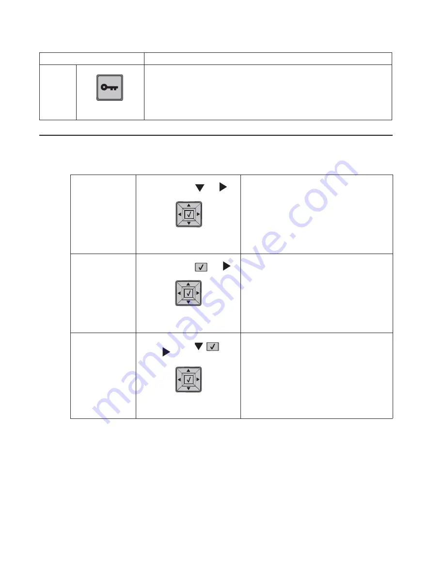
Diagnostics Mode
1. Turn off the printer.
2. Press and hold
and
.
3. Turn on the printer.
4. Release the buttons after 10
seconds.
The Diagnostics Mode group contains the settings
and operations used while manufacturing and
servicing the printer.
Configuration Menu
1. Turn off the printer.
2. Press and hold
and
.
3. Turn on the printer.
4. Release the buttons after 10
seconds.
The Configuration Menu group contains a set of
menus, settings, and operations which are
infrequently required by a user. Generally, the
options made available in this menu group are
used to configure a printer for operation.
See
“Configuration menu (CONFIG MENU)
Flash system code
mode
1. Turn off the printer.
2. Press and hold
,
,
and
.
3. Turn on the printer.
4. Release the buttons after 10
seconds.
Item
Description
Accessing service menus (models 5230n/dn, 5350dn, and 5530dn)
See
“Diagnostics mode (models 5230n/dn,
5350dn, and 5530dn)” on page 3-3
for more
information.
(models 5230n/dn, 5350dn, and 5530dn)” on
page 3-25
for more information.
Summary of Contents for 5230DN
Page 1: ... HOO Q GQ GQ GQ 6HUYLFH 0DQXDO 15 December 2009 ...
Page 2: ... ...
Page 14: ...xiv Service Manual ...
Page 19: ...Notices and safety information xix ...
Page 20: ...xx Service Manual ...
Page 34: ...1 10 Service Manual ...
Page 206: ...2 172 Service Manual ...
Page 318: ...3 112 Service Manual ...
Page 366: ...4 48 Service Manual 6 Remove the operator panel hinge assembly right ...
Page 369: ...Repair Information 4 51 9 Lift the operator panel door assembly out of the machine ...
Page 436: ...4 118 Service Manual 3 Remove the HCIT tray cover front A ...
Page 438: ...4 120 Service Manual 3 Remove the HCIT cover rear ...
Page 440: ...4 122 Service Manual 3 Remove the HCIT cover right ...
Page 469: ...Repair Information 4 151 5 Install the flash card into the system board ...
Page 518: ...4 200 Service Manual ...
Page 520: ...5 2 Service Manual ...
Page 524: ...7 2 Service Manual Assembly 1 Covers ...
Page 526: ...7 4 Service Manual Assembly 2 5230n dn 5350dn and 5530dn Operator panel ...
Page 528: ...7 6 Service Manual Assembly 3 T656dne Operator panel MPF and smart card ...
Page 530: ...7 8 Service Manual Assembly 4 Drive motor assemblies and duplex ...
Page 532: ...7 10 Service Manual Assembly 5 Media path and ducts 1 2 2 3 4 5 6 7 8 9 10 11 12 12 ...
Page 534: ...7 12 Service Manual Assembly 6 Printhead charge and transfer ...
Page 536: ...7 14 Service Manual Assembly 7 Pick arm assembly trays and MPF ...
Page 538: ...7 16 Service Manual Assembly 8 LVPS fuser and electrical cables 1 ...
Page 540: ...7 18 Service Manual Assembly 9 HVPS system card and electrical cables 2 ...
Page 548: ...7 26 Service Manual Assembly 13 SFP stapler assembly 1 1 ...
Page 552: ...7 30 Service Manual Assembly 15 SFP stapler assembly 3 4 5 1 2 3 6 6 7 8 9 10 11 ...
Page 554: ...7 32 Service Manual Assembly 16 SFP stapler assembly 4 1 2 ...
Page 556: ...7 34 Service Manual Assembly 17 5 bin mailbox 1 3 12 7 5 2 11 4 13 8 10 9 1 14 6 ...
Page 564: ...7 42 Service Manual Assembly 21 Envelope feeder and external duplex 1 2 ...
Page 582: ...I 12 Service Manual ...
Page 584: ...5230n dn Printer ...
Page 585: ...5 5 30dn Printer ...
Page 586: ...5 35 0dn Printer ...


