GASOLINE VEHICLE - ELECTRICAL
COMPONENTS
Starter/Generator
19
A
B
B
A
1
1
1
1
A
1
A
2
1
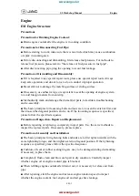
1. Measure each position in two places, 90 degrees apart
496
Figure 19-10
Inspect Commutator
ARMATURE GROUND TEST
CAUTION
• Do not submerge armature in solvent.
NOTE:
Before testing, wipe the armature with a clean cloth and remove carbon dust and metal particles from between
commutator bars.
Using a multimeter set on 200 ohms, place the positive (+) probe on the commutator bars and the negative (–) probe
on the armature core. The reading should be no continuity. If the reading is incorrect, replace the armature and the
two bearings
2020 Precedent,Villager 2 and 4 Maintenance and Service Manual
Page 19-11
Summary of Contents for DS Villager 4
Page 2: ......
Page 6: ......
Page 481: ...GASOLINE ENGINE HARNESS Wiring Diagrams Gasoline Engine Harness 26 ...
Page 482: ... Page intentionally left blank ...
Page 483: ...GASOLINE MAIN HARNESS Wiring Diagrams Gasoline Main Harness 26 ...
Page 484: ... Page intentionally left blank ...
Page 485: ...GASOLINE INSTRUMENT PANEL HARNESS Wiring Diagrams Gasoline Instrument Panel Harness 26 ...
Page 486: ... Page intentionally left blank ...
Page 488: ... Page intentionally left blank ...
Page 489: ...ELECTRIC MAIN HARNESS Wiring Diagrams Electric Main Harness 26 ...
Page 490: ... Page intentionally left blank ...
Page 492: ... Page intentionally left blank ...
Page 494: ... Page intentionally left blank ...
Page 495: ...ELECTRIC LIGHT HARNESS Wiring Diagrams Electric Light Harness 26 ...
Page 496: ... Page intentionally left blank ...
Page 497: ...ELECTRIC DC TO DC CONVERTER HARNESS Wiring Diagrams Electric DC to DC Converter Harness 26 ...
Page 498: ... Page intentionally left blank ...
Page 507: ...NOTES ...
Page 508: ...NOTES ...
Page 509: ......
Page 510: ......