18
Test Procedures
GASOLINE VEHICLE - TROUBLESHOOTING
AND ELECTRICAL SYSTEM
TEST PROCEDURE 12 – Voltage Regulator
NOTE:
This is a voltage test. Keep the battery connected while performing this test procedure.
1.
If necessary, see Testing Basics.
2.
Disable the vehicle.
3.
Set the Maintenance/Operate switch to MAINTENANCE.
4.
Make sure that the wires are connected correctly and are tight. If they are not, rewire or tighten as necessary.
5.
Check the engine RPM setting to make sure that it is adjusted correctly.
6.
Make sure that the battery is good and fully charged.
7.
Turn the key switch to ON.
8.
Operate the engine for several minutes to bring the voltage regulator to operating temperature.
9.
Turn the key switch to OFF position.
10.
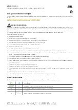
Make sure that the red wire from the voltage regulator (1) is connected to the solenoid (2).
R
E
D
2m
20
m
200
m
2k
200
200
200
200
20
2
200
m
500
20k
200k
2000
k
1000
OFF
WAVETEK
5XL
V
V
V
A
!
!
COM
200nA
MAX
1000 ---
750V
FUSED
2
1
463B
Figure 18-10
Voltage Regulator Test
11.
Set the multimeter to 20 VDC.
12.
Put the red (+) probe on the large post of the solenoid.
13.
Put the black (–) probe on the negative (–) battery post.
14.
Turn the key switch to the ON position.
15.
Press the accelerator to start the engine and run it at full governed speed.
15.1.
If the reading is between 14.7 and 15.3 volts, the voltage regulator is good.
15.2.
If the reading is over 15.3 volts and continues to rise, replace the voltage regulator.
15.3.
If the reading is lower than 14.7 volts but rising steadily, check the battery condition.
15.4.
If the reading is lower than 14.7 volts and not rising, check the starter/generator.
15.4.1.
If the starter/generator is good, replace the voltage regulator.
Page 18-20
2020 Precedent,Villager 2 and 4 Maintenance and Service Manual
Summary of Contents for DS Villager 4
Page 2: ......
Page 6: ......
Page 481: ...GASOLINE ENGINE HARNESS Wiring Diagrams Gasoline Engine Harness 26 ...
Page 482: ... Page intentionally left blank ...
Page 483: ...GASOLINE MAIN HARNESS Wiring Diagrams Gasoline Main Harness 26 ...
Page 484: ... Page intentionally left blank ...
Page 485: ...GASOLINE INSTRUMENT PANEL HARNESS Wiring Diagrams Gasoline Instrument Panel Harness 26 ...
Page 486: ... Page intentionally left blank ...
Page 488: ... Page intentionally left blank ...
Page 489: ...ELECTRIC MAIN HARNESS Wiring Diagrams Electric Main Harness 26 ...
Page 490: ... Page intentionally left blank ...
Page 492: ... Page intentionally left blank ...
Page 494: ... Page intentionally left blank ...
Page 495: ...ELECTRIC LIGHT HARNESS Wiring Diagrams Electric Light Harness 26 ...
Page 496: ... Page intentionally left blank ...
Page 497: ...ELECTRIC DC TO DC CONVERTER HARNESS Wiring Diagrams Electric DC to DC Converter Harness 26 ...
Page 498: ... Page intentionally left blank ...
Page 507: ...NOTES ...
Page 508: ...NOTES ...
Page 509: ......
Page 510: ......