15
Charger Operation
ELECTRIC VEHICLE - BATTERY CHARGER
2.
External Chargers:
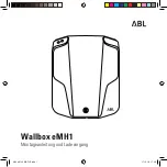
Insert the charger DC cord plug into the vehicle receptacle to begin a charge cycle. When
inserting the plug, align the raised guide on the plug with the guide slot in the receptacle and push straight in
slowly
.
3.
External Chargers:
The charger will turn on two to five seconds later, after the charger interlock function
activates. The charger interlock remains activated and prevents operation of the vehicle until the DC cord is
disconnected from the vehicle.
See following NOTE.
Onboard Chargers:
The charger will turn on two to five seconds later, after the charger interlock function
activates. The charger interlock remains activated and prevents operation of the vehicle until the AC cord is
disconnected from the AC outlet.
See following NOTE.
NOTE:
The dash-mounted charge indicator light will flash three times and the reverse buzzer simultaneously will
sound three times to indicate charging has begun. The number of flashes and beeps can vary depending on
the Beep Option setting.
See Beep Option, Section 11, Page 11-8.
4.
The charger monitors battery voltage, charge current and charge time to determine when the batteries are
properly charged. The charger will shut off by itself and the entire battery-shaped green light will stop flashing and
remain on. As long as the charger is allowed to shut off by itself, the batteries will be fully charged. Overcharging
and undercharging will normally be prevented.
5.
If the charger does not seem to be operating properly, or if the batteries seem weak, see Charger Troubleshooting
on page 15-14. If troubleshooting does not solve the issue, contact your local Club Car distributor/dealer.
66
Figure 15-8 Correct Insertion of External Charger DC Plug
67
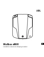
Figure 15-9
Incorrect Removal of External Charger DC
Plug
Page 15-12
2020 Precedent,Villager 2 and 4 Maintenance and Service Manual
Summary of Contents for DS Villager 4
Page 2: ......
Page 6: ......
Page 481: ...GASOLINE ENGINE HARNESS Wiring Diagrams Gasoline Engine Harness 26 ...
Page 482: ... Page intentionally left blank ...
Page 483: ...GASOLINE MAIN HARNESS Wiring Diagrams Gasoline Main Harness 26 ...
Page 484: ... Page intentionally left blank ...
Page 485: ...GASOLINE INSTRUMENT PANEL HARNESS Wiring Diagrams Gasoline Instrument Panel Harness 26 ...
Page 486: ... Page intentionally left blank ...
Page 488: ... Page intentionally left blank ...
Page 489: ...ELECTRIC MAIN HARNESS Wiring Diagrams Electric Main Harness 26 ...
Page 490: ... Page intentionally left blank ...
Page 492: ... Page intentionally left blank ...
Page 494: ... Page intentionally left blank ...
Page 495: ...ELECTRIC LIGHT HARNESS Wiring Diagrams Electric Light Harness 26 ...
Page 496: ... Page intentionally left blank ...
Page 497: ...ELECTRIC DC TO DC CONVERTER HARNESS Wiring Diagrams Electric DC to DC Converter Harness 26 ...
Page 498: ... Page intentionally left blank ...
Page 507: ...NOTES ...
Page 508: ...NOTES ...
Page 509: ......
Page 510: ......