


Chapter 6 — Adjustment Procedures
6-12
Part No. 750-184
periods with intervening purge periods than to risk
prolonged fuel introduction. If the pilot does not light
after several attempts, check all components of the pilot
system.
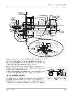
5. When the pilot flame is established, and with the
Pilot Adjusting
Cock
wide open, remove the
Flame Detector
from the burner
plate. The pilot flame can then be observed through this open-
ing.
!
Warning
Wear a protective shield or suitable glasses and keep eyes sufficiently
away from the sight tube opening to avoid serious personal injury or
death. Never remove the flame detector while the main burner is
firing. Failure to follow these instructions could result in serious
personal injury or death.
!
Warning
When checking the pilot flame, be aware the electrode is energized.
Failure to follow these instructions could result in serious personal
injury.
6. To make the final adjustment, slowly close the
Gas Pilot Adjust-
ing Cock
until the flame can no longer be seen through the sight
tube. Then slowly open the cock until a flame providing full sight
tube coverage is observed.
The adjustment must be accomplished within the time limit of the
safety switch or approximately 30 seconds after the detector is
removed. If the control shuts down, manually reset it. Replace the
detector and repeat the process from step 5.
7. When a suitable flame as indicated in paragraph 6 is obtained,
replace the detector. Observe the reading on the micro-ammeter.
The reading should be between 2-1/4 and 5 microamps when
using a lead sulfide detector and a standard amplifier. See the
flame signal table in the manufacturer's bulletin for values of
other combinations.
The flame signal indicated on the annunciator type relay should not
be less than 10 Vdc, and may be as high as 20 Vdc or greater.
The reading must be steady. If the reading fluctuates, recheck the
adjustment. Be sure that the flame detector is properly seated and
that the lens is clean.
8. Return the test switch to the RUN position.
9. If main flame has not been previously established, proceed to do
so in accordance with instructions elsewhere in the manual.
10. The reading of the main flame signal should also be checked.
Observe the flame signal for pilot alone, pilot and main burner
flame together and the main burner flame at high, low, and
intermediate firing rate positions. Readings should be steady and
in the range indicated in paragraph 7. If there are any devia-
Summary of Contents for CB Ohio Special 100 HP
Page 2: ...ii ...
Page 8: ...viii ...
Page 42: ...Chapter 2 Burner Operation and Control 2 22 Part No 750 184 ...
Page 116: ...Chapter 6 Adjustment Procedures 6 28 Part No 750 184 ...
Page 126: ...Chapter 8 Inspection and Maintenance 8 6 Part No 750 184 ...
Page 153: ...Chapter 9 Parts Part No 750 184 9 3 Insulated Front Head Model CB LE ...
Page 154: ...Chapter 9 Parts 9 4 Part No 750 184 Insulated Front Head Interior Model CB LE ...
Page 155: ...Chapter 9 Parts Part No 750 184 9 5 Insulated Inner Door Model CB OS ...
Page 156: ...Chapter 9 Parts 9 6 Part No 750 184 Insulated Rear Head CB LE ...
Page 157: ...Chapter 9 Parts Part No 750 184 9 7 Insulated Rear Head CB LE ...
Page 158: ...Chapter 9 Parts 9 8 Part No 750 184 Insulated Rear Head CB OS ...
Page 159: ...Chapter 9 Parts Part No 750 184 9 9 Dry Oven Model CB LE ...
Page 161: ...Chapter 9 Parts Part No 750 184 9 11 Motor Impeller Model CB LE ...
Page 162: ...Chapter 9 Parts 9 12 Part No 750 184 Front Head Linkage ...
Page 170: ...Chapter 9 Parts 9 20 Part No 750 184 Control Cabinet Hawk ICS ...
Page 171: ...Chapter 9 Parts Part No 750 184 9 21 Control Panel Standard ...
Page 172: ...Chapter 9 Parts 9 22 Part No 750 184 Entrance Box ...
Page 173: ...Chapter 9 Parts Part No 750 184 9 23 Front Head Electrical CB LE ...
Page 174: ...Chapter 9 Parts 9 24 Part No 750 184 Front Head Electrical CB LE ...
Page 175: ...Chapter 9 Parts Part No 750 184 9 25 Front Head Electrical CB OS ...
Page 176: ...Chapter 9 Parts 9 26 Part No 750 184 Front Head Electrical CB OS ...
Page 179: ...Chapter 9 Parts Part No 750 184 9 29 Heavy Oil Piping 60 Steam CB LE ...
Page 180: ...Chapter 9 Parts 9 30 Part No 750 184 Heavy Oil Piping 60 Steam CB LE SEE TABLE NEXT PAGE ...
Page 181: ...Chapter 9 Parts Part No 750 184 9 31 Common Oil Parts Heavy Oil ...
Page 182: ...Chapter 9 Parts 9 32 Part No 750 184 Side Mounted Air Compressor Piping ...
Page 183: ...Chapter 9 Parts Part No 750 184 9 33 Air Compressor Piping CB OS ...
Page 185: ...Chapter 9 Parts Part No 750 184 9 35 Light Oil Piping ...
Page 186: ...Chapter 9 Parts 9 36 Part No 750 184 Light Oil Air Piping Front Head ...
Page 187: ...Chapter 9 Parts Part No 750 184 9 37 Light Oil Air Piping Front Head PAGE 9 31 ...
Page 191: ...Chapter 9 Parts Part No 750 184 9 41 Gas Train 125 150 HP ...
Page 193: ...Chapter 9 Parts Part No 750 184 9 43 Gas Train 200 HP ...
Page 195: ...Chapter 9 Parts Part No 750 184 9 45 Steam Pressure Controls ...
Page 196: ...Chapter 9 Parts 9 46 Part No 750 184 Hot Water Temperature Controls ...
Page 197: ...Chapter 9 Parts Part No 750 184 9 47 Water Column ...
Page 198: ...Chapter 9 Parts 9 48 Part No 750 184 Water Column ...
Page 199: ...Chapter 9 Parts Part No 750 184 9 49 Fireside Gaskets CB LE ...
Page 200: ...Chapter 9 Parts 9 50 Part No 750 184 Fireside Gaskets CB OS ...


