


Chapter 6 — Adjustment Procedures
6-26
Part No. 750-184
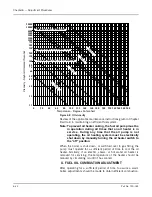
electrically removed from the circuit when a combination fuel
burner is fired on gas (Figure 6-18).
X. LOW-OIL-TEMPERATURE SWITCH
The L.O.T.S. prevents the burner from starting, or stops its
operation, if the temperature of the oil is below normal operating
temperature.
To adjust the control, insert a screwdriver into the center slot in the
control cover and turn the dial until the fixed (center) pointer is
approximately 30
°
F lower than the oil heater thermostat setting.
Turn the differential adjusting screw (located above dial) until the
movable indicator is approximately 5
°
F above the setting on the
main scale.
On a hot water boiler, the low-oil-temperature switch is an integral
part of the electric oil heater. The switch is non-adjustable and is
factory set at approximately 40
°
F below the maximum operating
temperature of the heater.
Y. HIGH-OIL-TEMPERATURE SWITCH
The H.O.T.S. prevents the burner from starting, or stops its
operation, if the temperature of the oil exceeds the normal operating
temperature.
To adjust, turn the dial until the pointer is approximately 25
°
F
above the normal operating temperature. The controls generally
have a set differential and will close 5
°
F below the setpoint.
Z. LOW OIL PRESSURE SWITCH
The L.O.P.S. prevents burner ignition, or stops its operation, when
the oil pressure is below the set point. Adjust the control by turning
the screw on top of control case to an indicated pressure 10 psi
below the established primary oil pressure setting indicated on the
oil supply pressure gauge. The switch will remain in a closed
position as long as the oil pressure exceeds this setting. The control
normally used automatically resets when pressure is restored after
a drop.
AA. ELECTRIC OIL HEATER THERMOSTAT (400 AND
600 SERIES - STEAM)
The maximum temperature setting of the control is stamped on the
dial. The maximum Temperature setting is attained with the
adjusting knob turned to the “high” end of the scale. Lower settings
are obtained by turning the adjusting knob clockwise using the
thermometer in the fuel oil controller as a guide.
The final setting of this thermostat should be at a temperature
approximately 15
°
F lower than the steam heater thermostat. This
eliminates the electric heater operation when the steam heater is
functioning. The electric heater is sized to provide sufficient heated
oil for low-fire operation on cold starts before steam is available.
Summary of Contents for CB Ohio Special 100 HP
Page 2: ...ii ...
Page 8: ...viii ...
Page 42: ...Chapter 2 Burner Operation and Control 2 22 Part No 750 184 ...
Page 116: ...Chapter 6 Adjustment Procedures 6 28 Part No 750 184 ...
Page 126: ...Chapter 8 Inspection and Maintenance 8 6 Part No 750 184 ...
Page 153: ...Chapter 9 Parts Part No 750 184 9 3 Insulated Front Head Model CB LE ...
Page 154: ...Chapter 9 Parts 9 4 Part No 750 184 Insulated Front Head Interior Model CB LE ...
Page 155: ...Chapter 9 Parts Part No 750 184 9 5 Insulated Inner Door Model CB OS ...
Page 156: ...Chapter 9 Parts 9 6 Part No 750 184 Insulated Rear Head CB LE ...
Page 157: ...Chapter 9 Parts Part No 750 184 9 7 Insulated Rear Head CB LE ...
Page 158: ...Chapter 9 Parts 9 8 Part No 750 184 Insulated Rear Head CB OS ...
Page 159: ...Chapter 9 Parts Part No 750 184 9 9 Dry Oven Model CB LE ...
Page 161: ...Chapter 9 Parts Part No 750 184 9 11 Motor Impeller Model CB LE ...
Page 162: ...Chapter 9 Parts 9 12 Part No 750 184 Front Head Linkage ...
Page 170: ...Chapter 9 Parts 9 20 Part No 750 184 Control Cabinet Hawk ICS ...
Page 171: ...Chapter 9 Parts Part No 750 184 9 21 Control Panel Standard ...
Page 172: ...Chapter 9 Parts 9 22 Part No 750 184 Entrance Box ...
Page 173: ...Chapter 9 Parts Part No 750 184 9 23 Front Head Electrical CB LE ...
Page 174: ...Chapter 9 Parts 9 24 Part No 750 184 Front Head Electrical CB LE ...
Page 175: ...Chapter 9 Parts Part No 750 184 9 25 Front Head Electrical CB OS ...
Page 176: ...Chapter 9 Parts 9 26 Part No 750 184 Front Head Electrical CB OS ...
Page 179: ...Chapter 9 Parts Part No 750 184 9 29 Heavy Oil Piping 60 Steam CB LE ...
Page 180: ...Chapter 9 Parts 9 30 Part No 750 184 Heavy Oil Piping 60 Steam CB LE SEE TABLE NEXT PAGE ...
Page 181: ...Chapter 9 Parts Part No 750 184 9 31 Common Oil Parts Heavy Oil ...
Page 182: ...Chapter 9 Parts 9 32 Part No 750 184 Side Mounted Air Compressor Piping ...
Page 183: ...Chapter 9 Parts Part No 750 184 9 33 Air Compressor Piping CB OS ...
Page 185: ...Chapter 9 Parts Part No 750 184 9 35 Light Oil Piping ...
Page 186: ...Chapter 9 Parts 9 36 Part No 750 184 Light Oil Air Piping Front Head ...
Page 187: ...Chapter 9 Parts Part No 750 184 9 37 Light Oil Air Piping Front Head PAGE 9 31 ...
Page 191: ...Chapter 9 Parts Part No 750 184 9 41 Gas Train 125 150 HP ...
Page 193: ...Chapter 9 Parts Part No 750 184 9 43 Gas Train 200 HP ...
Page 195: ...Chapter 9 Parts Part No 750 184 9 45 Steam Pressure Controls ...
Page 196: ...Chapter 9 Parts 9 46 Part No 750 184 Hot Water Temperature Controls ...
Page 197: ...Chapter 9 Parts Part No 750 184 9 47 Water Column ...
Page 198: ...Chapter 9 Parts 9 48 Part No 750 184 Water Column ...
Page 199: ...Chapter 9 Parts Part No 750 184 9 49 Fireside Gaskets CB LE ...
Page 200: ...Chapter 9 Parts 9 50 Part No 750 184 Fireside Gaskets CB OS ...


