


Chapter 6 — Adjustment Procedures
Part No. 750-184
6-27
BB. STEAM OIL HEATER THERMOSTAT (NO. 6 OIL)
(400 AND 600 SERIES - STEAM)
The maximum temperature setting of the control is stamped on the
dial. The maximum temperature setting is attained with the
adjusting knob turned to the “high” end of the scale. Lower settings
are obtained by turning the adjusting knob clockwise using the
thermometer in the fuel oil controller as a guide.
The final setting of the thermostat should provide oil at a sufficient
temperature for efficient combustion based on flue gas analysis.
There is no need to heat the oil in excess of the temperature.
CC. HOT WATER OIL HEATER THERMOSTAT (400 AND
600 SERIES)
To adjust the thermostat, insert a screwdriver into the center slot in
the control cover and turn the dial until the pointer is at the desired
temperature level. The control generally has a set differential, and
will close 5
°
F below the setpoint.
The thermostat contacts close to energize the booster water pump,
which pumps water from the boiler through the heater. On cold
starts, it is normal practice to manually close the valve in the pump
discharge line until the boiler water temperature exceeds the
temperature of fuel oil entering the heater.
The electric oil heater on a hot water boiler burning No. 6 oil and
equipped with a hot water oil heater has a built-in adjustable
thermostat. The maximum temperature setting is stamped on its
dial. The desired temperature can be obtained by turning the
adjusting screw. The thermostat should be set at a temperature
approximately 15 degrees lower than the hot water heater
thermostat. Such a temperature prevents the electric heater from
operation when the water heater is functioning. The electric heater
is sized to provide sufficient heated oil for low-fire operation on cold
starts before hot water is available.
DD. STEAM HEATER PRESSURE REGULATOR (400
AND 600 SERIES - STEAM)
The regulator is provided on a boiler designed to operate at
pressures above 15 psi and reduces boiler steam pressure to the
level necessary for proper operation of the steam oil heater. The
pressure should be reduced to a point that permits sufficient
temperature to heat the oil, while allowing as continuous a steam
flow as possible. Pressure that is too high will result in frequent
cycling of the steam solenoid valve.
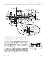
It is best to adjust the regulator under typical flow conditions. To do
so, it is suggested that the globe valve in the steam supply line be
closed so that there is no pressure on the regulator. Turn out the
adjusting screw fully to relieve compression on the regulator spring,
thus closing the regulator. With steam at normal pressure, open the
globe valve and then set the secondary pressure by turning the
adjusting screw or handle until the downstream gauge shows the
desired pressure.
Summary of Contents for CB Ohio Special 100 HP
Page 2: ...ii ...
Page 8: ...viii ...
Page 42: ...Chapter 2 Burner Operation and Control 2 22 Part No 750 184 ...
Page 116: ...Chapter 6 Adjustment Procedures 6 28 Part No 750 184 ...
Page 126: ...Chapter 8 Inspection and Maintenance 8 6 Part No 750 184 ...
Page 153: ...Chapter 9 Parts Part No 750 184 9 3 Insulated Front Head Model CB LE ...
Page 154: ...Chapter 9 Parts 9 4 Part No 750 184 Insulated Front Head Interior Model CB LE ...
Page 155: ...Chapter 9 Parts Part No 750 184 9 5 Insulated Inner Door Model CB OS ...
Page 156: ...Chapter 9 Parts 9 6 Part No 750 184 Insulated Rear Head CB LE ...
Page 157: ...Chapter 9 Parts Part No 750 184 9 7 Insulated Rear Head CB LE ...
Page 158: ...Chapter 9 Parts 9 8 Part No 750 184 Insulated Rear Head CB OS ...
Page 159: ...Chapter 9 Parts Part No 750 184 9 9 Dry Oven Model CB LE ...
Page 161: ...Chapter 9 Parts Part No 750 184 9 11 Motor Impeller Model CB LE ...
Page 162: ...Chapter 9 Parts 9 12 Part No 750 184 Front Head Linkage ...
Page 170: ...Chapter 9 Parts 9 20 Part No 750 184 Control Cabinet Hawk ICS ...
Page 171: ...Chapter 9 Parts Part No 750 184 9 21 Control Panel Standard ...
Page 172: ...Chapter 9 Parts 9 22 Part No 750 184 Entrance Box ...
Page 173: ...Chapter 9 Parts Part No 750 184 9 23 Front Head Electrical CB LE ...
Page 174: ...Chapter 9 Parts 9 24 Part No 750 184 Front Head Electrical CB LE ...
Page 175: ...Chapter 9 Parts Part No 750 184 9 25 Front Head Electrical CB OS ...
Page 176: ...Chapter 9 Parts 9 26 Part No 750 184 Front Head Electrical CB OS ...
Page 179: ...Chapter 9 Parts Part No 750 184 9 29 Heavy Oil Piping 60 Steam CB LE ...
Page 180: ...Chapter 9 Parts 9 30 Part No 750 184 Heavy Oil Piping 60 Steam CB LE SEE TABLE NEXT PAGE ...
Page 181: ...Chapter 9 Parts Part No 750 184 9 31 Common Oil Parts Heavy Oil ...
Page 182: ...Chapter 9 Parts 9 32 Part No 750 184 Side Mounted Air Compressor Piping ...
Page 183: ...Chapter 9 Parts Part No 750 184 9 33 Air Compressor Piping CB OS ...
Page 185: ...Chapter 9 Parts Part No 750 184 9 35 Light Oil Piping ...
Page 186: ...Chapter 9 Parts 9 36 Part No 750 184 Light Oil Air Piping Front Head ...
Page 187: ...Chapter 9 Parts Part No 750 184 9 37 Light Oil Air Piping Front Head PAGE 9 31 ...
Page 191: ...Chapter 9 Parts Part No 750 184 9 41 Gas Train 125 150 HP ...
Page 193: ...Chapter 9 Parts Part No 750 184 9 43 Gas Train 200 HP ...
Page 195: ...Chapter 9 Parts Part No 750 184 9 45 Steam Pressure Controls ...
Page 196: ...Chapter 9 Parts 9 46 Part No 750 184 Hot Water Temperature Controls ...
Page 197: ...Chapter 9 Parts Part No 750 184 9 47 Water Column ...
Page 198: ...Chapter 9 Parts 9 48 Part No 750 184 Water Column ...
Page 199: ...Chapter 9 Parts Part No 750 184 9 49 Fireside Gaskets CB LE ...
Page 200: ...Chapter 9 Parts 9 50 Part No 750 184 Fireside Gaskets CB OS ...


