


Chapter 6 — Adjustment Procedures
Part No. 750-184
6-15
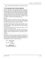
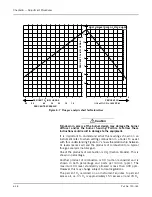
Pressure Correction
The flow rate outlined in Section P is based on a “base” pressure,
which is usually atmospheric or 14.7 psia.
Meters generally measure gas in cubic feet at “line” or supply
pressure. To convert the volume obtained from a meter reading into
cubic feet at base pressure, it is necessary to multiply the meter
index reading by the correction factor obtained from Table 6-4.
Conversely:
To determine what the meter index reading should be in order to
provide the volume of gas required for input, divide the desired flow
rate by the proper pressure correction factor. This answer indicates
the number of cubic feet at line pressure which must pass through
the meter to deliver the equivalent number of cubic feet at base
pressure.
As an example:
Assume that a 200 horsepower boiler is installed at 2,000 feet
above sea level; is equipped with a standard gas train and a high
turndown burner; and that 1,000 Btu natural gas is available with
an incoming gas pressure of 3 psig. The pressure and flow
requirements can be determined as follows:
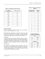
Table 6-4 Pressure Correction
Factors
REGULATOR INLET
PRESSURE (PSIG)
PRESSURE
FACTOR
1
1.05
2
1.11
3
1.18
4
1.25
5
1.32
6
1.39
7
1.45
8
1.53
9
1.59
10
1.66
11
1.72
12
1.81
13
1.86
14
1.93
15
2.00
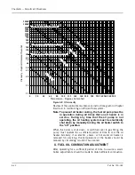
Table 6-5 Altitude Correction Factors
ALTITUDE
FEET ABOVE SEA LEVEL
CORRECTION FACTOR
1000
1.04
2000
1.07
2500
1.09
3000
1.11
4000
1.16
5000
1.21
6000
1.25
7000
1.30
8000
1.35
9000
1.40
Table 6-6 Max. gas
consumption (natural gas)
CB-LE
HP
FT
3
/HR
125
5103
150
6124
200
8165
CB OHIO SPECIAL
HP
FT
3
/HR
125S
5230
150S
6280
175S
7350
200S
8370
225S
9415
Summary of Contents for CB Ohio Special 100 HP
Page 2: ...ii ...
Page 8: ...viii ...
Page 42: ...Chapter 2 Burner Operation and Control 2 22 Part No 750 184 ...
Page 116: ...Chapter 6 Adjustment Procedures 6 28 Part No 750 184 ...
Page 126: ...Chapter 8 Inspection and Maintenance 8 6 Part No 750 184 ...
Page 153: ...Chapter 9 Parts Part No 750 184 9 3 Insulated Front Head Model CB LE ...
Page 154: ...Chapter 9 Parts 9 4 Part No 750 184 Insulated Front Head Interior Model CB LE ...
Page 155: ...Chapter 9 Parts Part No 750 184 9 5 Insulated Inner Door Model CB OS ...
Page 156: ...Chapter 9 Parts 9 6 Part No 750 184 Insulated Rear Head CB LE ...
Page 157: ...Chapter 9 Parts Part No 750 184 9 7 Insulated Rear Head CB LE ...
Page 158: ...Chapter 9 Parts 9 8 Part No 750 184 Insulated Rear Head CB OS ...
Page 159: ...Chapter 9 Parts Part No 750 184 9 9 Dry Oven Model CB LE ...
Page 161: ...Chapter 9 Parts Part No 750 184 9 11 Motor Impeller Model CB LE ...
Page 162: ...Chapter 9 Parts 9 12 Part No 750 184 Front Head Linkage ...
Page 170: ...Chapter 9 Parts 9 20 Part No 750 184 Control Cabinet Hawk ICS ...
Page 171: ...Chapter 9 Parts Part No 750 184 9 21 Control Panel Standard ...
Page 172: ...Chapter 9 Parts 9 22 Part No 750 184 Entrance Box ...
Page 173: ...Chapter 9 Parts Part No 750 184 9 23 Front Head Electrical CB LE ...
Page 174: ...Chapter 9 Parts 9 24 Part No 750 184 Front Head Electrical CB LE ...
Page 175: ...Chapter 9 Parts Part No 750 184 9 25 Front Head Electrical CB OS ...
Page 176: ...Chapter 9 Parts 9 26 Part No 750 184 Front Head Electrical CB OS ...
Page 179: ...Chapter 9 Parts Part No 750 184 9 29 Heavy Oil Piping 60 Steam CB LE ...
Page 180: ...Chapter 9 Parts 9 30 Part No 750 184 Heavy Oil Piping 60 Steam CB LE SEE TABLE NEXT PAGE ...
Page 181: ...Chapter 9 Parts Part No 750 184 9 31 Common Oil Parts Heavy Oil ...
Page 182: ...Chapter 9 Parts 9 32 Part No 750 184 Side Mounted Air Compressor Piping ...
Page 183: ...Chapter 9 Parts Part No 750 184 9 33 Air Compressor Piping CB OS ...
Page 185: ...Chapter 9 Parts Part No 750 184 9 35 Light Oil Piping ...
Page 186: ...Chapter 9 Parts 9 36 Part No 750 184 Light Oil Air Piping Front Head ...
Page 187: ...Chapter 9 Parts Part No 750 184 9 37 Light Oil Air Piping Front Head PAGE 9 31 ...
Page 191: ...Chapter 9 Parts Part No 750 184 9 41 Gas Train 125 150 HP ...
Page 193: ...Chapter 9 Parts Part No 750 184 9 43 Gas Train 200 HP ...
Page 195: ...Chapter 9 Parts Part No 750 184 9 45 Steam Pressure Controls ...
Page 196: ...Chapter 9 Parts 9 46 Part No 750 184 Hot Water Temperature Controls ...
Page 197: ...Chapter 9 Parts Part No 750 184 9 47 Water Column ...
Page 198: ...Chapter 9 Parts 9 48 Part No 750 184 Water Column ...
Page 199: ...Chapter 9 Parts Part No 750 184 9 49 Fireside Gaskets CB LE ...
Page 200: ...Chapter 9 Parts 9 50 Part No 750 184 Fireside Gaskets CB OS ...


