


Chapter 5 — Starting and Operating Instructions
5-8
Part No. 750-184
that at maximum firing rate a minimum reading of 75 psi is
obtained on the oil supply pressure gauge.
The other pressure adjustments are to the regulators on the fuel oil
controller. Both the pressure regulating and the back pressure relief
valves are equipped with tubing that directs and adds atomizing air
pressure to the adjustable spring pressure. Since the air pump is not
running at this time, only tentative adjustments can be made.
Without the air supply, adjust the fuel oil pressure regulator so that
the burner oil gauge registers approximately 35 psi. Adjust the back
pressure relief valve so that its gauge reads about 10 psi less than
the burner gauge.
The pressure gauges will indicate higher readings when a flame is
present. The pressure will increase as the firing rate increases. The
pressure reading on the two gauges on the controller will, despite
the fluctuation, retain a nearly constant difference of 10 psi.
Final regulation of oil flow to the nozzle can be done, if necessary,
by adjusting the metering cam screws as outlined in Chapter 6.
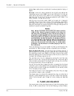
Suggested oil pressures at high fire operation:
!
Caution
Before turning on the electric oil heater switch, be certain that the
heater shell is filled with fuel oil and the flow is established. Failure
to follow these instructions could result in equipment damage.
Oil Temperature
- After determining that the heater shell is filled
and that fuel oil circulation exists, turn the oil heater switch to “on.”
Adjust the electric oil heater thermostat to maintain oil temperature
at approximately 200
°
F.
The electric heater on burners equipped for No. 6 fuel oil is sized
so that it is capable of supplying heated oil at a rate no greater than
that required for low fire operation and is primarily supplied for
convenience on cold starts. Heating coils utilizing either steam or
hot water are supplied to provide sufficient heat so that higher rates
of firing can be accomplished once steam pressure or hot water is
available. In normal operation, the thermostat governing the electric
heating element is kept at a lower setting than the thermostat
governing admission of steam to the heater, or of hot water
circulation, so that heating is not performed electrically except when
steam or hot water is not available.
Set the steam thermostat or the hot water thermostat to maintain
an oil temperature of 220-230
°
F. The electric heater will be turned
off automatically as soon as steam or hot water provides heat.
Note: The temperatures listed are tentative. The composition of the
fuel oil in a given grade can vary, necessitating a higher or
lower preheating temperature. The viscosity of the oil at the
nozzle should be less than 300 SSU and preferably less than
Oil Supply at the Fuel Oil Controller
75 psi
Regulated Oil Pressure Gauge
30-45 psi
Summary of Contents for CB Ohio Special 100 HP
Page 2: ...ii ...
Page 8: ...viii ...
Page 42: ...Chapter 2 Burner Operation and Control 2 22 Part No 750 184 ...
Page 116: ...Chapter 6 Adjustment Procedures 6 28 Part No 750 184 ...
Page 126: ...Chapter 8 Inspection and Maintenance 8 6 Part No 750 184 ...
Page 153: ...Chapter 9 Parts Part No 750 184 9 3 Insulated Front Head Model CB LE ...
Page 154: ...Chapter 9 Parts 9 4 Part No 750 184 Insulated Front Head Interior Model CB LE ...
Page 155: ...Chapter 9 Parts Part No 750 184 9 5 Insulated Inner Door Model CB OS ...
Page 156: ...Chapter 9 Parts 9 6 Part No 750 184 Insulated Rear Head CB LE ...
Page 157: ...Chapter 9 Parts Part No 750 184 9 7 Insulated Rear Head CB LE ...
Page 158: ...Chapter 9 Parts 9 8 Part No 750 184 Insulated Rear Head CB OS ...
Page 159: ...Chapter 9 Parts Part No 750 184 9 9 Dry Oven Model CB LE ...
Page 161: ...Chapter 9 Parts Part No 750 184 9 11 Motor Impeller Model CB LE ...
Page 162: ...Chapter 9 Parts 9 12 Part No 750 184 Front Head Linkage ...
Page 170: ...Chapter 9 Parts 9 20 Part No 750 184 Control Cabinet Hawk ICS ...
Page 171: ...Chapter 9 Parts Part No 750 184 9 21 Control Panel Standard ...
Page 172: ...Chapter 9 Parts 9 22 Part No 750 184 Entrance Box ...
Page 173: ...Chapter 9 Parts Part No 750 184 9 23 Front Head Electrical CB LE ...
Page 174: ...Chapter 9 Parts 9 24 Part No 750 184 Front Head Electrical CB LE ...
Page 175: ...Chapter 9 Parts Part No 750 184 9 25 Front Head Electrical CB OS ...
Page 176: ...Chapter 9 Parts 9 26 Part No 750 184 Front Head Electrical CB OS ...
Page 179: ...Chapter 9 Parts Part No 750 184 9 29 Heavy Oil Piping 60 Steam CB LE ...
Page 180: ...Chapter 9 Parts 9 30 Part No 750 184 Heavy Oil Piping 60 Steam CB LE SEE TABLE NEXT PAGE ...
Page 181: ...Chapter 9 Parts Part No 750 184 9 31 Common Oil Parts Heavy Oil ...
Page 182: ...Chapter 9 Parts 9 32 Part No 750 184 Side Mounted Air Compressor Piping ...
Page 183: ...Chapter 9 Parts Part No 750 184 9 33 Air Compressor Piping CB OS ...
Page 185: ...Chapter 9 Parts Part No 750 184 9 35 Light Oil Piping ...
Page 186: ...Chapter 9 Parts 9 36 Part No 750 184 Light Oil Air Piping Front Head ...
Page 187: ...Chapter 9 Parts Part No 750 184 9 37 Light Oil Air Piping Front Head PAGE 9 31 ...
Page 191: ...Chapter 9 Parts Part No 750 184 9 41 Gas Train 125 150 HP ...
Page 193: ...Chapter 9 Parts Part No 750 184 9 43 Gas Train 200 HP ...
Page 195: ...Chapter 9 Parts Part No 750 184 9 45 Steam Pressure Controls ...
Page 196: ...Chapter 9 Parts 9 46 Part No 750 184 Hot Water Temperature Controls ...
Page 197: ...Chapter 9 Parts Part No 750 184 9 47 Water Column ...
Page 198: ...Chapter 9 Parts 9 48 Part No 750 184 Water Column ...
Page 199: ...Chapter 9 Parts Part No 750 184 9 49 Fireside Gaskets CB LE ...
Page 200: ...Chapter 9 Parts 9 50 Part No 750 184 Fireside Gaskets CB OS ...


