


Chapter 8 — Inspection and Maintenance
8-18
Part No. 750-184
Lubricating Oil Strainer and Cooling Coil
Air pressure from the pump forces lubricating oil from the tank through a
cooling tube to the pump. The oil lubricates the pump bearings and also
provides a seal and lubrication for the pump vanes.
The cooled oil flows to the pump through the strainer in the filler pipe. It is
possible to visually verify oil flow during operation by removing the filler cap
and checking the flow. If necessary, the strainer may be cleaned during
operation.
In the event it is necessary to clean the strainer during operation, clean it
and replace immediately. It can be cleaned by immersing in solvent and
blowing it dry with compressed air. Do not operate without the strainer any
longer than necessary, and never add new oil unless it is in place. A spare
strainer basket can be obtained, if desired, and used on a rotating basis
while the other is serviced.
Air Cleaner
Never operate the air pump without the air cleaner in place. The cleaner
itself must be periodically checked and its element flushed and cleaned
semi-annually.
Air-Oil Tank
Pads of steel wool are used in the air to oil tank as a filtering medium to
separate the lube oil from the compressed air. The pads play a very
important role and should be replaced semi-annually. It is also important
that a proper grade of steel wool be used. Only No. 3 coarse grade American
steel wool or equal (CB919-124) should be used. Three pads are required.
When replacing the wool, insert two pads into the cylinder. Alternate the
grain of the pads. Install the spacer with its stub end toward the opening and
fit one pad over the stub. Be careful not to overly compress the wool and be
sure that it is fluffed out to fill all available space. Improper packing can
cause high oil consumption. After the last pad is in place, slip the retainer
screen onto the cylinder. Be sure to fit an O-ring gasket under the cover so
that a tight seal is obtained.
Follow previous instructions for oil replacement.
Lube Oil Cooling Coil
The fins on the tubing must be kept clean and free of any dust or dirt that
would resist air flow and cause overheating. Use an air hose to blow away
debris. Internal cleaning of the tubes is seldom required if a good quality
lube oil is used.
Flexible Coupling Alignment
Alignment of the pump and motor through the flexible coupling is extremely
important for trouble-free operation. Check the coupling alignment semi-
annually and replace the coupling insert as required. Keep the coupling
guard in place.
The most commonly used tools for checking alignment are a small
straightedge and a thickness gauge.
Summary of Contents for CB Ohio Special 100 HP
Page 2: ...ii ...
Page 8: ...viii ...
Page 42: ...Chapter 2 Burner Operation and Control 2 22 Part No 750 184 ...
Page 116: ...Chapter 6 Adjustment Procedures 6 28 Part No 750 184 ...
Page 126: ...Chapter 8 Inspection and Maintenance 8 6 Part No 750 184 ...
Page 153: ...Chapter 9 Parts Part No 750 184 9 3 Insulated Front Head Model CB LE ...
Page 154: ...Chapter 9 Parts 9 4 Part No 750 184 Insulated Front Head Interior Model CB LE ...
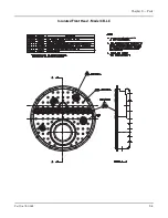
Page 155: ...Chapter 9 Parts Part No 750 184 9 5 Insulated Inner Door Model CB OS ...
Page 156: ...Chapter 9 Parts 9 6 Part No 750 184 Insulated Rear Head CB LE ...
Page 157: ...Chapter 9 Parts Part No 750 184 9 7 Insulated Rear Head CB LE ...
Page 158: ...Chapter 9 Parts 9 8 Part No 750 184 Insulated Rear Head CB OS ...
Page 159: ...Chapter 9 Parts Part No 750 184 9 9 Dry Oven Model CB LE ...
Page 161: ...Chapter 9 Parts Part No 750 184 9 11 Motor Impeller Model CB LE ...
Page 162: ...Chapter 9 Parts 9 12 Part No 750 184 Front Head Linkage ...
Page 170: ...Chapter 9 Parts 9 20 Part No 750 184 Control Cabinet Hawk ICS ...
Page 171: ...Chapter 9 Parts Part No 750 184 9 21 Control Panel Standard ...
Page 172: ...Chapter 9 Parts 9 22 Part No 750 184 Entrance Box ...
Page 173: ...Chapter 9 Parts Part No 750 184 9 23 Front Head Electrical CB LE ...
Page 174: ...Chapter 9 Parts 9 24 Part No 750 184 Front Head Electrical CB LE ...
Page 175: ...Chapter 9 Parts Part No 750 184 9 25 Front Head Electrical CB OS ...
Page 176: ...Chapter 9 Parts 9 26 Part No 750 184 Front Head Electrical CB OS ...
Page 179: ...Chapter 9 Parts Part No 750 184 9 29 Heavy Oil Piping 60 Steam CB LE ...
Page 180: ...Chapter 9 Parts 9 30 Part No 750 184 Heavy Oil Piping 60 Steam CB LE SEE TABLE NEXT PAGE ...
Page 181: ...Chapter 9 Parts Part No 750 184 9 31 Common Oil Parts Heavy Oil ...
Page 182: ...Chapter 9 Parts 9 32 Part No 750 184 Side Mounted Air Compressor Piping ...
Page 183: ...Chapter 9 Parts Part No 750 184 9 33 Air Compressor Piping CB OS ...
Page 185: ...Chapter 9 Parts Part No 750 184 9 35 Light Oil Piping ...
Page 186: ...Chapter 9 Parts 9 36 Part No 750 184 Light Oil Air Piping Front Head ...
Page 187: ...Chapter 9 Parts Part No 750 184 9 37 Light Oil Air Piping Front Head PAGE 9 31 ...
Page 191: ...Chapter 9 Parts Part No 750 184 9 41 Gas Train 125 150 HP ...
Page 193: ...Chapter 9 Parts Part No 750 184 9 43 Gas Train 200 HP ...
Page 195: ...Chapter 9 Parts Part No 750 184 9 45 Steam Pressure Controls ...
Page 196: ...Chapter 9 Parts 9 46 Part No 750 184 Hot Water Temperature Controls ...
Page 197: ...Chapter 9 Parts Part No 750 184 9 47 Water Column ...
Page 198: ...Chapter 9 Parts 9 48 Part No 750 184 Water Column ...
Page 199: ...Chapter 9 Parts Part No 750 184 9 49 Fireside Gaskets CB LE ...
Page 200: ...Chapter 9 Parts 9 50 Part No 750 184 Fireside Gaskets CB OS ...


