


Chapter 2 — Burner Operation and Control
2-4
Part No. 750-184
B. CONTROL AND COMPONENT FUNCTION
The term “control” covers the more impor tant valves and
components, including but not limited to electrical controls or those
monitored by the program relay. The operator must become familiar
with the individual functioning of all controls before understanding
boiler operation and procedures outlined in this manual.
The actual controls furnished with any given boiler will depend upon
the type of fuel for which it is equipped, and whether it is a hot
water or steam boiler. Refer to the applicable group or groups within
Chapter 2 that apply to the particular boiler.
Boilers with optional features may have control components not
listed here.
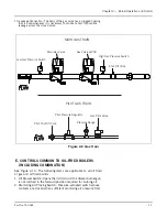
C. COMPONENTS COMMON TO ALL BOILERS
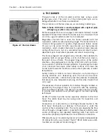
1. Forced Draft Fan Motor (Figure 2-5): Drives the forced draft fan
directly to provide combustion air. Also referred to as a blower
motor.
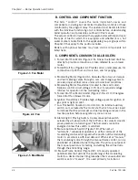
2. Forced Draft Fan (Figure 2-6): Provides all air, under pressure, for
combustion of pilot fuel and main fuel, and for purging.
3. Modulating Motor (Figure 2-6): Operates the rotary air damper
and fuel metering valves through a cam and linkage system to
provide proper air/fuel ratios under all boiler load conditions.
4. Modulating Motor Transformer (located in the mod motor):
Reduces control circuit voltage (115 Vac) to required voltage
(24Vac) for operation of the modulating motor.
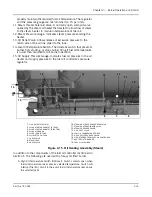
5. Forced Draft Fan Motor Starter (Figure 2-9 & 2-10): Energizes
forced draft fan (blower) motor.
6. Ignition Transformer: Provides high voltage spark for ignition of
gas pilot or light oil pilot.
7. Low Fire Switch (located in mod motor): An internal auxiliary
switch, cam actuated by the motor shaft, which must be closed
to indicate that the air damper and fuel metering valve are in the
low fire position before an ignition cycle can occur.
8. Atomizing Air Proving Switch: A pressure-sensitive switch
actuated by air pressure from the Air Pump. Its contacts close to
prove presence of atomizing air. The fuel valves cannot be
energized unless this switch is satisfied.
9. Manual-Automatic Switch (Figure 2-8): When set at
“automatic,” subsequent operation is at the command of the
modulating control, which governs the position of the modulating
motor in accordance with load demand. When set at “manual,”
the modulating motor, through the manual flame control, can be
positioned at a desired burner firing rate. The primary purpose of
the manual position is for testing and setting the air/fuel ratio
through the entire firing range.
10.Manual Flame Control (Figure 2-8): A manually operated
potentiometer that permits the positioning of the modulating
motor to a desired burner firing rate when the manual-automatic
switch is set on “manual“. It is used primarily for initial or
Figure 2-3 Fan Motor
Figure 2-4 Fan
Figure 2-5 Mod Motor
Summary of Contents for CB Ohio Special 100 HP
Page 2: ...ii ...
Page 8: ...viii ...
Page 42: ...Chapter 2 Burner Operation and Control 2 22 Part No 750 184 ...
Page 116: ...Chapter 6 Adjustment Procedures 6 28 Part No 750 184 ...
Page 126: ...Chapter 8 Inspection and Maintenance 8 6 Part No 750 184 ...
Page 153: ...Chapter 9 Parts Part No 750 184 9 3 Insulated Front Head Model CB LE ...
Page 154: ...Chapter 9 Parts 9 4 Part No 750 184 Insulated Front Head Interior Model CB LE ...
Page 155: ...Chapter 9 Parts Part No 750 184 9 5 Insulated Inner Door Model CB OS ...
Page 156: ...Chapter 9 Parts 9 6 Part No 750 184 Insulated Rear Head CB LE ...
Page 157: ...Chapter 9 Parts Part No 750 184 9 7 Insulated Rear Head CB LE ...
Page 158: ...Chapter 9 Parts 9 8 Part No 750 184 Insulated Rear Head CB OS ...
Page 159: ...Chapter 9 Parts Part No 750 184 9 9 Dry Oven Model CB LE ...
Page 161: ...Chapter 9 Parts Part No 750 184 9 11 Motor Impeller Model CB LE ...
Page 162: ...Chapter 9 Parts 9 12 Part No 750 184 Front Head Linkage ...
Page 170: ...Chapter 9 Parts 9 20 Part No 750 184 Control Cabinet Hawk ICS ...
Page 171: ...Chapter 9 Parts Part No 750 184 9 21 Control Panel Standard ...
Page 172: ...Chapter 9 Parts 9 22 Part No 750 184 Entrance Box ...
Page 173: ...Chapter 9 Parts Part No 750 184 9 23 Front Head Electrical CB LE ...
Page 174: ...Chapter 9 Parts 9 24 Part No 750 184 Front Head Electrical CB LE ...
Page 175: ...Chapter 9 Parts Part No 750 184 9 25 Front Head Electrical CB OS ...
Page 176: ...Chapter 9 Parts 9 26 Part No 750 184 Front Head Electrical CB OS ...
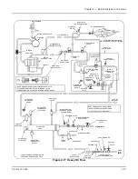
Page 179: ...Chapter 9 Parts Part No 750 184 9 29 Heavy Oil Piping 60 Steam CB LE ...
Page 180: ...Chapter 9 Parts 9 30 Part No 750 184 Heavy Oil Piping 60 Steam CB LE SEE TABLE NEXT PAGE ...
Page 181: ...Chapter 9 Parts Part No 750 184 9 31 Common Oil Parts Heavy Oil ...
Page 182: ...Chapter 9 Parts 9 32 Part No 750 184 Side Mounted Air Compressor Piping ...
Page 183: ...Chapter 9 Parts Part No 750 184 9 33 Air Compressor Piping CB OS ...
Page 185: ...Chapter 9 Parts Part No 750 184 9 35 Light Oil Piping ...
Page 186: ...Chapter 9 Parts 9 36 Part No 750 184 Light Oil Air Piping Front Head ...
Page 187: ...Chapter 9 Parts Part No 750 184 9 37 Light Oil Air Piping Front Head PAGE 9 31 ...
Page 191: ...Chapter 9 Parts Part No 750 184 9 41 Gas Train 125 150 HP ...
Page 193: ...Chapter 9 Parts Part No 750 184 9 43 Gas Train 200 HP ...
Page 195: ...Chapter 9 Parts Part No 750 184 9 45 Steam Pressure Controls ...
Page 196: ...Chapter 9 Parts 9 46 Part No 750 184 Hot Water Temperature Controls ...
Page 197: ...Chapter 9 Parts Part No 750 184 9 47 Water Column ...
Page 198: ...Chapter 9 Parts 9 48 Part No 750 184 Water Column ...
Page 199: ...Chapter 9 Parts Part No 750 184 9 49 Fireside Gaskets CB LE ...
Page 200: ...Chapter 9 Parts 9 50 Part No 750 184 Fireside Gaskets CB OS ...


