


Chapter 2 — Burner Operation and Control
2-6
Part No. 750-184
19.Program Relay and Flame Safeguard Control: Automatically
programs each starting, operating and shutdown period in
conjunction with operating limit and interlock devices. Includes,
in a timed and proper sequence, the operation of the blower
motor, ignition system, fuel valve(s), and the damper motor. The
sequence includes air purge periods prior to ignition and upon
burner shutdown.
The flame detector portion of the control monitors both oil and gas
flames and provides protection in the event of loss of a flame signal.
The control recycles automatically during normal operation, or
following a power interruption. It must be manually reset following
a safety shutdown caused by a loss of flame. An internal checking
circuit, effective on every start, prevents burner operation in the
event anything causes the flame relay to hold in during this period.
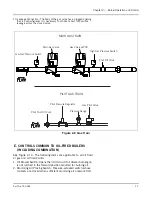
D. CONTROLS FOR GAS FIRING
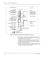
See Figure 2-9. Depending upon the requirements of the insurance
carrier or other governing agencies, the gas flow control system
components may vary. Refer to the Dimension Diagram (DD)
prepared by Cleaver-Brooks for your specified installation.
1. Gas Pilot Valve: A solenoid valve that opens during the ignition period
to admit fuel to the pilot. It closes after main flame is established. The
sequence of energizing and de-energizing is controlled by the
programming relay. A second gas pilot valve may be required by
insurance regulations.
2. Gas Pilot Shutoff Cock: For manually opening or closing the gas supply
to gas pilot valve.
3. Gas Pressure Gauge: Indicates gas pressure to pilot.
4. Gas Pressure Regulating Valve: Reduces incoming gas pressure to suit
the pilot.
5. Main Gas Cock: For manually opening and closing the main fuel gas
supply downstream of the main gas line pressure regulator. A second
shutoff cock, downstream of the main gas valve(s), is installed to
provide a means of shutting off the gas line whenever a test is made for
leakage across the main gas valve.
6. Butterfly Gas Valve: The pivoted disc in the valve is actuated by
connecting linkage from the gas modulating cam to regulate the rate of
gas flow to the burner.
7. Main Gas Valves: Electrically actuated shutoff valves that open
simultaneously to admit gas to the burner. The downstream valve is
equipped with a “proof of closure” switch that is connected into the pre-
ignition interlock circuit.
8. Low Gas Pressure Switch: A pressure-actuated switch that is closed
whenever main gas line pressure is above a preselected pressure.
Should the pressure drop below the setting, the switch contacts open a
circuit causing the main gas valve(s) to close, or prevent the burner
from starting. The switch is usually equipped with a device that must
be manually reset after being tripped.
9. High Gas Pressure Switch: A pressure actuated switch that is closed
whenever main gas line pressure is below a preselected pressure.
Should the pressure rise above the setting, the switch contacts will
open a circuit causing the main gas valve(s) to close, or prevent the
burner from starting. The switch is usually equipped with a device that
must be manually reset after being tripped.
Summary of Contents for CB Ohio Special 100 HP
Page 2: ...ii ...
Page 8: ...viii ...
Page 42: ...Chapter 2 Burner Operation and Control 2 22 Part No 750 184 ...
Page 116: ...Chapter 6 Adjustment Procedures 6 28 Part No 750 184 ...
Page 126: ...Chapter 8 Inspection and Maintenance 8 6 Part No 750 184 ...
Page 153: ...Chapter 9 Parts Part No 750 184 9 3 Insulated Front Head Model CB LE ...
Page 154: ...Chapter 9 Parts 9 4 Part No 750 184 Insulated Front Head Interior Model CB LE ...
Page 155: ...Chapter 9 Parts Part No 750 184 9 5 Insulated Inner Door Model CB OS ...
Page 156: ...Chapter 9 Parts 9 6 Part No 750 184 Insulated Rear Head CB LE ...
Page 157: ...Chapter 9 Parts Part No 750 184 9 7 Insulated Rear Head CB LE ...
Page 158: ...Chapter 9 Parts 9 8 Part No 750 184 Insulated Rear Head CB OS ...
Page 159: ...Chapter 9 Parts Part No 750 184 9 9 Dry Oven Model CB LE ...
Page 161: ...Chapter 9 Parts Part No 750 184 9 11 Motor Impeller Model CB LE ...
Page 162: ...Chapter 9 Parts 9 12 Part No 750 184 Front Head Linkage ...
Page 170: ...Chapter 9 Parts 9 20 Part No 750 184 Control Cabinet Hawk ICS ...
Page 171: ...Chapter 9 Parts Part No 750 184 9 21 Control Panel Standard ...
Page 172: ...Chapter 9 Parts 9 22 Part No 750 184 Entrance Box ...
Page 173: ...Chapter 9 Parts Part No 750 184 9 23 Front Head Electrical CB LE ...
Page 174: ...Chapter 9 Parts 9 24 Part No 750 184 Front Head Electrical CB LE ...
Page 175: ...Chapter 9 Parts Part No 750 184 9 25 Front Head Electrical CB OS ...
Page 176: ...Chapter 9 Parts 9 26 Part No 750 184 Front Head Electrical CB OS ...
Page 179: ...Chapter 9 Parts Part No 750 184 9 29 Heavy Oil Piping 60 Steam CB LE ...
Page 180: ...Chapter 9 Parts 9 30 Part No 750 184 Heavy Oil Piping 60 Steam CB LE SEE TABLE NEXT PAGE ...
Page 181: ...Chapter 9 Parts Part No 750 184 9 31 Common Oil Parts Heavy Oil ...
Page 182: ...Chapter 9 Parts 9 32 Part No 750 184 Side Mounted Air Compressor Piping ...
Page 183: ...Chapter 9 Parts Part No 750 184 9 33 Air Compressor Piping CB OS ...
Page 185: ...Chapter 9 Parts Part No 750 184 9 35 Light Oil Piping ...
Page 186: ...Chapter 9 Parts 9 36 Part No 750 184 Light Oil Air Piping Front Head ...
Page 187: ...Chapter 9 Parts Part No 750 184 9 37 Light Oil Air Piping Front Head PAGE 9 31 ...
Page 191: ...Chapter 9 Parts Part No 750 184 9 41 Gas Train 125 150 HP ...
Page 193: ...Chapter 9 Parts Part No 750 184 9 43 Gas Train 200 HP ...
Page 195: ...Chapter 9 Parts Part No 750 184 9 45 Steam Pressure Controls ...
Page 196: ...Chapter 9 Parts 9 46 Part No 750 184 Hot Water Temperature Controls ...
Page 197: ...Chapter 9 Parts Part No 750 184 9 47 Water Column ...
Page 198: ...Chapter 9 Parts 9 48 Part No 750 184 Water Column ...
Page 199: ...Chapter 9 Parts Part No 750 184 9 49 Fireside Gaskets CB LE ...
Page 200: ...Chapter 9 Parts 9 50 Part No 750 184 Fireside Gaskets CB OS ...


