


Chapter 6 — Adjustment Procedures
6-24
Part No. 750-184
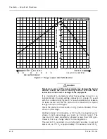
the oil modulating cam to obtain a constant fuel/air ratio through
the entire firing range.
Note: Be sure the to loosen the cam foot locking screws
before adjusting any cam screws or the cam feet may be
damaged.
Since the input of combustion air is ordinarily fixed at any given
point in the modulating cycle, the flue gas reading is determined by
varying the input of fuel at that setting. The adjustment is made to
the metering cam by means of adjusting screws, which are turned
out (counterclockwise from hex-socket end) to increase the flow of
fuel and in (clockwise from hex-socket end) to decrease it. Flow rate
is highest when the cam follower assembly is closest to the
jackshaft.
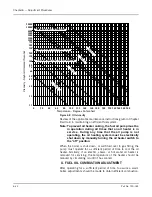
If oil pressure, primary air pressure, and linkages are properly
adjusted, the metering cam should require minimal adjustment.
Using the flame control switch, position the cam so that the
adjusting screw adjacent to the end, high-fire screw, contacts the
cam follower. Make a combustion analysis at this point.
If an adjustment is necessar y, turn the adjustment screw
accordingly to increase or decrease fuel flow. Take a combustion
reading to verify input. Repeat as necessary until the desired flow is
obtained. Continue this pressure, stopping at each adjusting screw,
until the low fire position is reached.
Note: Do not use any lubricant on the adjusting setscrews.
These have a nylon locking insert intended to provide
locking torque and resistance to loosening and a
lubricant could damage the equipment.
Standard Burner Low Fire Adjustment (Heavy Oil)
The fuel input should be adjusted with the low fire cam screw, to
approximately 25% of that at high fire. At low fire the O
2
flue gas
reading should be between 7- 8%.
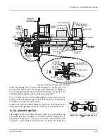
V. BURNER DRAWER ADJUSTMENT
There are relatively few adjustments that can be made to the
burner; however, a check should be made to assure that all
components are properly located, and that all holding screws are
properly tightened. The diffuser location on gas fired boilers is quite
important. There should be 1/4” distance between the edges of the
diffuser fins and gas outlet tubes (spuds). The setting of an oil fired
burner is less exacting; the diffuser should be located with the skirt
approximately 1-1/8” from the end of the burner tube.
When the proper diffuser location is ascertained, the setting of the
nozzle in relation to the diffuser should be checked. This generally
is set at time of manufacture and seldom needs altering. It is most
important that oil spray does not impinge upon the diffuser. The
distance that the nozzle is behind the diffuser has some latitude,
and individual installations may require a slight deviation. Refer to
Figure 6-10 for initial setup dimensions.
Summary of Contents for CB Ohio Special 100 HP
Page 2: ...ii ...
Page 8: ...viii ...
Page 42: ...Chapter 2 Burner Operation and Control 2 22 Part No 750 184 ...
Page 116: ...Chapter 6 Adjustment Procedures 6 28 Part No 750 184 ...
Page 126: ...Chapter 8 Inspection and Maintenance 8 6 Part No 750 184 ...
Page 153: ...Chapter 9 Parts Part No 750 184 9 3 Insulated Front Head Model CB LE ...
Page 154: ...Chapter 9 Parts 9 4 Part No 750 184 Insulated Front Head Interior Model CB LE ...
Page 155: ...Chapter 9 Parts Part No 750 184 9 5 Insulated Inner Door Model CB OS ...
Page 156: ...Chapter 9 Parts 9 6 Part No 750 184 Insulated Rear Head CB LE ...
Page 157: ...Chapter 9 Parts Part No 750 184 9 7 Insulated Rear Head CB LE ...
Page 158: ...Chapter 9 Parts 9 8 Part No 750 184 Insulated Rear Head CB OS ...
Page 159: ...Chapter 9 Parts Part No 750 184 9 9 Dry Oven Model CB LE ...
Page 161: ...Chapter 9 Parts Part No 750 184 9 11 Motor Impeller Model CB LE ...
Page 162: ...Chapter 9 Parts 9 12 Part No 750 184 Front Head Linkage ...
Page 170: ...Chapter 9 Parts 9 20 Part No 750 184 Control Cabinet Hawk ICS ...
Page 171: ...Chapter 9 Parts Part No 750 184 9 21 Control Panel Standard ...
Page 172: ...Chapter 9 Parts 9 22 Part No 750 184 Entrance Box ...
Page 173: ...Chapter 9 Parts Part No 750 184 9 23 Front Head Electrical CB LE ...
Page 174: ...Chapter 9 Parts 9 24 Part No 750 184 Front Head Electrical CB LE ...
Page 175: ...Chapter 9 Parts Part No 750 184 9 25 Front Head Electrical CB OS ...
Page 176: ...Chapter 9 Parts 9 26 Part No 750 184 Front Head Electrical CB OS ...
Page 179: ...Chapter 9 Parts Part No 750 184 9 29 Heavy Oil Piping 60 Steam CB LE ...
Page 180: ...Chapter 9 Parts 9 30 Part No 750 184 Heavy Oil Piping 60 Steam CB LE SEE TABLE NEXT PAGE ...
Page 181: ...Chapter 9 Parts Part No 750 184 9 31 Common Oil Parts Heavy Oil ...
Page 182: ...Chapter 9 Parts 9 32 Part No 750 184 Side Mounted Air Compressor Piping ...
Page 183: ...Chapter 9 Parts Part No 750 184 9 33 Air Compressor Piping CB OS ...
Page 185: ...Chapter 9 Parts Part No 750 184 9 35 Light Oil Piping ...
Page 186: ...Chapter 9 Parts 9 36 Part No 750 184 Light Oil Air Piping Front Head ...
Page 187: ...Chapter 9 Parts Part No 750 184 9 37 Light Oil Air Piping Front Head PAGE 9 31 ...
Page 191: ...Chapter 9 Parts Part No 750 184 9 41 Gas Train 125 150 HP ...
Page 193: ...Chapter 9 Parts Part No 750 184 9 43 Gas Train 200 HP ...
Page 195: ...Chapter 9 Parts Part No 750 184 9 45 Steam Pressure Controls ...
Page 196: ...Chapter 9 Parts 9 46 Part No 750 184 Hot Water Temperature Controls ...
Page 197: ...Chapter 9 Parts Part No 750 184 9 47 Water Column ...
Page 198: ...Chapter 9 Parts 9 48 Part No 750 184 Water Column ...
Page 199: ...Chapter 9 Parts Part No 750 184 9 49 Fireside Gaskets CB LE ...
Page 200: ...Chapter 9 Parts 9 50 Part No 750 184 Fireside Gaskets CB OS ...


