Chapter 7 - Troubleshooting
Part No. 750-184
7-1
Chapter 7
Troubleshooting
Note: If your boiler is equipped with a CB-
HAWK ICS boiler control system, refer to
M a n u a l N o . 7 5 0 - 2 2 9 f o r s p e c i f i c
i n f o r m a t i o n r e g a r d i n g p r o c e d u r e s
described in this section
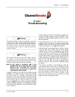
Chapter 7 assumes that the unit has been properly
installed and adjusted, and that it has been running
for some time. It is further assumed that the
operator has become thoroughly familiar with both
burner and manual by this time. The points under
each heading are set down briefly as possible
causes, suggestions or clues to simplify locating the
source of trouble. Methods of correcting the trouble,
once it has been identified, may be found elsewhere
in this manual.
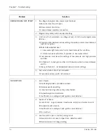
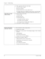
If the burner will not start or operate properly, the
trouble shooting chapter should be referred to for
assistance in pinpointing problems that may not be
readily apparent.
The program relay has the capability to self-
diagnose and to display a code or message that
indicates the failure condition. Refer to the control
bulletin for specifics and suggested remedies.
Familiarity with the programmer and other controls
in the system may be obtained by studying the
contents of this manual. Knowledge of the system
and its controls will make trouble shooting much
easier. Costly down-time or delays can be prevented
by systematic checks of actual operation against the
normal sequence to determine the stage at which
performance deviates from normal. Following a
routine may possibly eliminate overlooking an
obvious condition, often one that is relatively simple
to correct.
If an obvious condition is not apparent, check the
continuity of the circuits with a voltmeter or test
lamp. Each circuit can be checked and the fault
isolated and corrected. Most circuitry checking can
be done between appropriate terminals on the
terminal boards in the control cabinet or the
entrance box. Refer to the schematic wiring
diagram for terminal identification.
Trouble shooting should be performed only by
personnel who are familiar with the equipment
and who have read and understand the contents
o f t h i s m a n u a l . Fa i l u r e t o f o l l o w t h e s e
instructions could result in serious personal
injury or death
Disconnect and lock out the main power supply
in order to avoid the hazard of electrical
shock.Failure to follow these instructions could
result in serious personal injury or death
!
Warning
!
Warning
Summary of Contents for CB Ohio Special 100 HP
Page 2: ...ii ...
Page 8: ...viii ...
Page 42: ...Chapter 2 Burner Operation and Control 2 22 Part No 750 184 ...
Page 116: ...Chapter 6 Adjustment Procedures 6 28 Part No 750 184 ...
Page 126: ...Chapter 8 Inspection and Maintenance 8 6 Part No 750 184 ...
Page 153: ...Chapter 9 Parts Part No 750 184 9 3 Insulated Front Head Model CB LE ...
Page 154: ...Chapter 9 Parts 9 4 Part No 750 184 Insulated Front Head Interior Model CB LE ...
Page 155: ...Chapter 9 Parts Part No 750 184 9 5 Insulated Inner Door Model CB OS ...
Page 156: ...Chapter 9 Parts 9 6 Part No 750 184 Insulated Rear Head CB LE ...
Page 157: ...Chapter 9 Parts Part No 750 184 9 7 Insulated Rear Head CB LE ...
Page 158: ...Chapter 9 Parts 9 8 Part No 750 184 Insulated Rear Head CB OS ...
Page 159: ...Chapter 9 Parts Part No 750 184 9 9 Dry Oven Model CB LE ...
Page 161: ...Chapter 9 Parts Part No 750 184 9 11 Motor Impeller Model CB LE ...
Page 162: ...Chapter 9 Parts 9 12 Part No 750 184 Front Head Linkage ...
Page 170: ...Chapter 9 Parts 9 20 Part No 750 184 Control Cabinet Hawk ICS ...
Page 171: ...Chapter 9 Parts Part No 750 184 9 21 Control Panel Standard ...
Page 172: ...Chapter 9 Parts 9 22 Part No 750 184 Entrance Box ...
Page 173: ...Chapter 9 Parts Part No 750 184 9 23 Front Head Electrical CB LE ...
Page 174: ...Chapter 9 Parts 9 24 Part No 750 184 Front Head Electrical CB LE ...
Page 175: ...Chapter 9 Parts Part No 750 184 9 25 Front Head Electrical CB OS ...
Page 176: ...Chapter 9 Parts 9 26 Part No 750 184 Front Head Electrical CB OS ...
Page 179: ...Chapter 9 Parts Part No 750 184 9 29 Heavy Oil Piping 60 Steam CB LE ...
Page 180: ...Chapter 9 Parts 9 30 Part No 750 184 Heavy Oil Piping 60 Steam CB LE SEE TABLE NEXT PAGE ...
Page 181: ...Chapter 9 Parts Part No 750 184 9 31 Common Oil Parts Heavy Oil ...
Page 182: ...Chapter 9 Parts 9 32 Part No 750 184 Side Mounted Air Compressor Piping ...
Page 183: ...Chapter 9 Parts Part No 750 184 9 33 Air Compressor Piping CB OS ...
Page 185: ...Chapter 9 Parts Part No 750 184 9 35 Light Oil Piping ...
Page 186: ...Chapter 9 Parts 9 36 Part No 750 184 Light Oil Air Piping Front Head ...
Page 187: ...Chapter 9 Parts Part No 750 184 9 37 Light Oil Air Piping Front Head PAGE 9 31 ...
Page 191: ...Chapter 9 Parts Part No 750 184 9 41 Gas Train 125 150 HP ...
Page 193: ...Chapter 9 Parts Part No 750 184 9 43 Gas Train 200 HP ...
Page 195: ...Chapter 9 Parts Part No 750 184 9 45 Steam Pressure Controls ...
Page 196: ...Chapter 9 Parts 9 46 Part No 750 184 Hot Water Temperature Controls ...
Page 197: ...Chapter 9 Parts Part No 750 184 9 47 Water Column ...
Page 198: ...Chapter 9 Parts 9 48 Part No 750 184 Water Column ...
Page 199: ...Chapter 9 Parts Part No 750 184 9 49 Fireside Gaskets CB LE ...
Page 200: ...Chapter 9 Parts 9 50 Part No 750 184 Fireside Gaskets CB OS ...

