Chapter 3 — Waterside Care and Requirements
3-10
Part No. 750-184
may begin, the burner should be ready for firing. The operator must
be familiar with the procedure outlined under burner operation.
!
Warning
Use of a suitable face mask, goggles, rubber gloves, and protective
garments must be worn when handling or mixing caustic chemicals.
Do not permit the dry material or the concentrated solution to come
in contact with skin or clothing. Failure to follow these instructions
could result in serious personal injury or death.
Your local Cleaver-Brooks authorized representative will be able to
recommend a cleaning or boil-out procedure. In the event such
ser vice is unavailable or is yet unscheduled, the following
information may be of assistance.
There are several chemicals suitable for boil-out. One combination
often used is soda ash (sodium carbonate) and caustic soda
(sodium hydroxide) at the rate of 3 to 5 pounds each per 1,000
pounds of water, along with a small amount of laundry detergent
added as a wetting agent.
The suggested general procedure for cleaning a boiler is as follows:
(1) Refer to Table 3-2 to determine water capacity. Have sufficient
cleaning material on hand to complete the job.
(2) When dissolving chemicals, the following procedure is
suggested. Warm water should be put into a suitable container.
Slowly introduce the dry chemical into the water, stirring it at all
times until the chemical is completely dissolved. Add the chemical
slowly and in small amounts to prevent excessive heat and
turbulence.
(3) An over-flow pipe should be attached to one of the top boiler
openings and routed to a safe point of discharge. A relief or safety
valve tapping is usually used.
(4) Water relief valves and steam safety valves must be removed
before adding the boil-out solution so that neither it nor the grease
which it may carry will contaminate the valves. Use care in
removing and reinstalling the valves.
Table 3-2
Water Capacity and Weight
s
(5) All valves in the piping leading to or from the system must be
closed to prevent the cleaning solution from getting into the system.
GENERATOR
SIZES
CB & CB-LE
WATER – GALLONS
WATER – WEIGHT
NORMAL FLOODED NORMAL
FLOODED
125 HP
689
920
5750
7670
150 HP
869
1115
7250
9295
200 HP
1034
1335
8625
11130
Summary of Contents for CB Ohio Special 100 HP
Page 2: ...ii ...
Page 8: ...viii ...
Page 42: ...Chapter 2 Burner Operation and Control 2 22 Part No 750 184 ...
Page 116: ...Chapter 6 Adjustment Procedures 6 28 Part No 750 184 ...
Page 126: ...Chapter 8 Inspection and Maintenance 8 6 Part No 750 184 ...
Page 153: ...Chapter 9 Parts Part No 750 184 9 3 Insulated Front Head Model CB LE ...
Page 154: ...Chapter 9 Parts 9 4 Part No 750 184 Insulated Front Head Interior Model CB LE ...
Page 155: ...Chapter 9 Parts Part No 750 184 9 5 Insulated Inner Door Model CB OS ...
Page 156: ...Chapter 9 Parts 9 6 Part No 750 184 Insulated Rear Head CB LE ...
Page 157: ...Chapter 9 Parts Part No 750 184 9 7 Insulated Rear Head CB LE ...
Page 158: ...Chapter 9 Parts 9 8 Part No 750 184 Insulated Rear Head CB OS ...
Page 159: ...Chapter 9 Parts Part No 750 184 9 9 Dry Oven Model CB LE ...
Page 161: ...Chapter 9 Parts Part No 750 184 9 11 Motor Impeller Model CB LE ...
Page 162: ...Chapter 9 Parts 9 12 Part No 750 184 Front Head Linkage ...
Page 170: ...Chapter 9 Parts 9 20 Part No 750 184 Control Cabinet Hawk ICS ...
Page 171: ...Chapter 9 Parts Part No 750 184 9 21 Control Panel Standard ...
Page 172: ...Chapter 9 Parts 9 22 Part No 750 184 Entrance Box ...
Page 173: ...Chapter 9 Parts Part No 750 184 9 23 Front Head Electrical CB LE ...
Page 174: ...Chapter 9 Parts 9 24 Part No 750 184 Front Head Electrical CB LE ...
Page 175: ...Chapter 9 Parts Part No 750 184 9 25 Front Head Electrical CB OS ...
Page 176: ...Chapter 9 Parts 9 26 Part No 750 184 Front Head Electrical CB OS ...
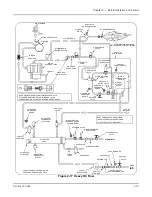
Page 179: ...Chapter 9 Parts Part No 750 184 9 29 Heavy Oil Piping 60 Steam CB LE ...
Page 180: ...Chapter 9 Parts 9 30 Part No 750 184 Heavy Oil Piping 60 Steam CB LE SEE TABLE NEXT PAGE ...
Page 181: ...Chapter 9 Parts Part No 750 184 9 31 Common Oil Parts Heavy Oil ...
Page 182: ...Chapter 9 Parts 9 32 Part No 750 184 Side Mounted Air Compressor Piping ...
Page 183: ...Chapter 9 Parts Part No 750 184 9 33 Air Compressor Piping CB OS ...
Page 185: ...Chapter 9 Parts Part No 750 184 9 35 Light Oil Piping ...
Page 186: ...Chapter 9 Parts 9 36 Part No 750 184 Light Oil Air Piping Front Head ...
Page 187: ...Chapter 9 Parts Part No 750 184 9 37 Light Oil Air Piping Front Head PAGE 9 31 ...
Page 191: ...Chapter 9 Parts Part No 750 184 9 41 Gas Train 125 150 HP ...
Page 193: ...Chapter 9 Parts Part No 750 184 9 43 Gas Train 200 HP ...
Page 195: ...Chapter 9 Parts Part No 750 184 9 45 Steam Pressure Controls ...
Page 196: ...Chapter 9 Parts 9 46 Part No 750 184 Hot Water Temperature Controls ...
Page 197: ...Chapter 9 Parts Part No 750 184 9 47 Water Column ...
Page 198: ...Chapter 9 Parts 9 48 Part No 750 184 Water Column ...
Page 199: ...Chapter 9 Parts Part No 750 184 9 49 Fireside Gaskets CB LE ...
Page 200: ...Chapter 9 Parts 9 50 Part No 750 184 Fireside Gaskets CB OS ...


