


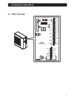


6.1 PCB (Terminal)
ON
OFF
PCB
(TERMINAL)
3
4
2
1
Remote
Controller
1
2
3
4
5
6
7
17
18
19
20
21
22
23
Humidity
Sensor
COM
DHW Remote
Contact
ON/OFF
or
EHS Alarm
GND
24VAC
COM
Control
DHW
T.probe
OUTDOOR
T.probe
BUFFER
T.probe
Mix water
T.probe
3-way
mixing
valve
RS485
+
-
Dehumidifier
Alarm
Pump1
Pump2
Neutral
N.C.
Neutral
EHS
Heating
Cooling
mode
output
Phase
Signal
3-way
valve
8
9
10
11
12
13
14
Dual Set
Point
Control
Heating
Cooling
mode
Flow
switch
Night
mode
Low
tariff
RS485
GND
45
46
47
48
49
50
31
32
24
25
26
27
28
29
30
15
16
N
41
42
43
44
51
52
Electric
heater
Reset
SW.
Pump
SW.
49
6. Electrical connections
Summary of Contents for AEYC-0639U-CH
Page 156: ...20810030 M ...