


148
11. Service and Maintenance
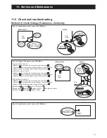
[Fig. 4] Voltage of Pump on the PCB (Main)
17
Pump
Fuse CF2
(250V T3.15A)
PCB
(Main)
Between white and black ,approx. AC200~370V
Between brown and black ,approx. DC3~7V
Between red and black ,approx. DC15V
PCB (Main) is normal
W
B
R
BR
BL
13
Fuse CF2
(250V T5A)
0Ω
Pump
PCB
(Main)
[1639U]
[0639U,1039U]
8
1.4kΩ
4-way valve coil
PCB
(Main)
10
4way valve coil
PCB
(Main)
[Fig. 5] Resistance of the 4way valve coil
Take off the connector and check the resistance 4way valve coil.
[1639U]
[0639U,1039U]
Measure voltage between the connector pins of connector
17
.
Connector
17
shall be checked during Heating or Cooling operation.
Measure voltage as follows without taking off the connector
17
.
Measure voltage between the connector pins of connector
13
.
Connector
13
shall be checked during Heating or Cooling operation.
Measure voltage as follows without taking off the connector
13
.
Pump (0639U,1039U)
Pump (1639U)
9
260~300Ω
PCB
(Main)
11
PCB
(Main)
Defrost heater
[Fig. 6] Resistance of the Defrost heater
[1639U]
[0639U,1039U]
Summary of Contents for AEYC-0639U-CH
Page 156: ...20810030 M ...