


147
11. Service and Maintenance
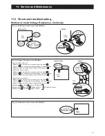
[Fig. 1] Continuity of current Fuse on the PCB (Main)
14
11
BL Y W B R
LOWER:
Fuse CF6
UPPER:
Fuse CF7
(250V T3.15A)
0Ω
Fan motor
PCB
(Main)
PCB
(Main)
Fuse CF1
(250V T30A)
0Ω
Fuse CF3
(250V 3A)
0Ω
Fuse CF4
(250V 3A)
PCB
(Main)
Fuse CF3
(250V 3A)
Fuse CF1
0639U : 250V 15A
1039U : 250V 25A
18
Fan motor
PCB
(Main)
Fuse CF7
(250V T3.15A)
[1639U]
[0639U,1039U]
[Fig. 2] Voltage of Fan motor on the PCB (Main)
Measure voltage between the connector pins of connector
11
.
Connector
11
shall be checked during Heating or Cooling operation.
Measure voltage as follows without taking off the connector
11
.
Measure voltage between the connector pins of connector
18
.
Connector
18
shall be checked during Heating or Cooling operation.
Measure voltage as follows without taking off the connector
18
.
Measure voltage between the connector pins of connector
14
.
Connector
14
shall be checked during Heating or Cooling operation.
Measure voltage as follows without taking off the connector
14
.
Between red and black , approx. DC200~370V
Between yellow and black , approx. DC3~7V
Between white and black , approx. DC15V
PCB (Main) is normal
LOWER Fan motor (1639U)
Fan motor (0639U,1039U)
UPPER Fan motor (1639U)
[1639U]
[0639U,1039U]
PCB
(Main)
Fuse CF6
0639U : 250V 15A
1039U : 250V 25A
[Fig. 3] Continuity of current Fuse on the PCB (Main)
11.5 Check and troubleshooting
Method of check Voltage, Resistance, Continuity
Summary of Contents for AEYC-0639U-CH
Page 156: ...20810030 M ...