


145
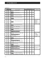
11. Service and Maintenance
Error
codes
Appearance, Portion, Parts
seemed wrong
Method of check
Troubleshooting
Figure/
Table
Error
reset
U1
Compressor
overheat
protection relay
operation
(1639U)
Compressor overheat
protection relay
Check the resistance by tester If Compressor overheat protection
relay blown, it should be replaced
Fig. 8
Manual
Gas leakage
Check the service valve and
refrigerant circuit (pipe)
Correct refrigerant once, then
recharge with prescribed mass
Not cool down
Not warm up
Fuse CF2
0639U : 250V T3.15A
1039U : 250V T3.15A
1639U : 250V T5A
Check the electric continuity of
Fuse CF1 by tester
If CF2 is blown,it should be replaced
and check the resistance of 4way
valve and the resistance of Defrost
heater by tester
Fig. 7
4way valve
Check the resistance of 4way
valve by tester
If 4way valve is blown,it should be
replaced
Fig. 5
Defrost heater
Check the resistance of
Defrost heater by tester
If Defrost heater is blown,it should be
replaced
Fig. 6
Short cycle (insufficient
air circulation)
Check the blockage of air inlet
& outlet
Ensure the installation position to
avoid blockage of air inlet & outlet
Sensor,Temp. Outgo-
ing water and Return
water
Check the resistance by tester If any of these sensors is faulty, it
should be replaced
Table 4
Gas leakage
Check the service valve and
refrigerant circuit (pipe)
After fixing the leakage point,collect
the refrigerant once,then recharge
with prescribed mass
Clogged water circuit
Check temperature difference
of Outgoing/Return water
(see Monitor display function)
Large difference means flow
rate is too low
Remove the blockage,then restart
operation
PCB(Controller) and PCB(Terminal) alarms
Error
codes
Appearance, Portion, Parts
seemed wrong
Method of check
Troubleshooting
Figure/
Table
Error
reset
L0
EEPROM error PCB(Controller) and
PCB(EEPROM)
PCB(Controller) and PCB(EEPROM)
should be replaced
Power
OFF
L1
DHW temp.
sensor error
Sensor,Temp.
DHW tank
Check the resistance by tester If the sensor is faulty, it should be
replaced
Table 3
Auto
L2
Outdoor temp.
sensor error
Sensor,Temp.Outdoor
(Additional)
Check the resistance by tester If the sensor is faulty, it should be
replaced
Table 5
L3
Buffer temp.
sensor error
Sensor,Temp.
Buffer tank
Check the resistance by tester If the sensor is faulty, it should be
replaced
Table 3
L4
Mix water temp.
sensor error
Sensor,Temp.
Mix water
Check the resistance by tester If the sensor is faulty, it should be
replaced
Table 3
L5
Humidity sen-
sor error
Sensor, Humidity
Check the resistance by tester If the sensor is faulty, it should be
replaced
Fig. 9
Manual
L6
Flow switch
error
Clogged the water
pump and/or water
circuit
Check the pump and the water
circuit
Remove any obstructions, clean the
water filter, unblock the pump
Flow switch
Other than described above
Flow switch should be replaced
L7
Mixing valve
error
Clogged the water
pump and/or water
circuit
Check the pump and the water
circuit
Remove any obstructions,clean the
water filter, unblock the pump
PCB(Terminal)
Check the voltage by tester
PCB(Terminal) should be replaced
Fig. 10,11
Mixing valve
Other than described above
Mixing valve should be replaced
Summary of Contents for AEYC-0639U-CH
Page 156: ...20810030 M ...