


Chapter 2
2-15
F-2-56
6) Close the cassette.
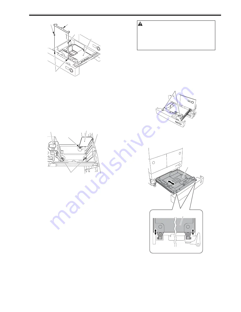
2.2.18 Changing the Media Size of the Front Deck (Left/
Right)
0015-4674
iR5065 / iR 5055 / iR5075 / iR5075N / iR5065N / iR5055N
1) Hold down the release button to slide the deck out.
2) Remove one of each screw [4] of the trailing edge plate [1], the left guide
plate [2] and the right guide plate [3]. Secure the each guide plate in place
on user desired size.
Factory setting: A4 size
3) After changing the size, place the paper and set the deck into the host ma-
chine.
F-2-57
4) Attach the new media size label onto the media size plate of the deck.
5) In case the size is changed, register the front deck media size in service
mode.
Right deck: COPIER > OPTION > CST > P-SZ-C1
Left deck: COPIER > OPTION > CST > P-SZ-C2
A4=6, B5=15, and LTR=18
2.2.19 Image/Operation Check in User Mode
0015-4675
iR5065 / iR 5055 / iR5075 / iR5075N / iR5065N / iR5055N
1) Press [Reset] twice and return to the main screen. Using test sheet, check
the copy operation and copy image.
- Copy operation: Check to see that the copy operation is appropriate.
- Duplexing copy operation: Check to see that the paper feeding at the
duplexing unit is appropriate.
- Pickup operation: Check to see that the paper is fed normally from the
each pickup slot.
- Operation noise: Check to see that there is no abnormal noise.
- Fixed ratio reproduction: Check the image quality for each fixed ratio
reproduction.
- Multiple copies: Check to see that the copy operation for a specified
number of sheets is appropriate.
- Check to see that print images picked up from each cassette/deck are
within the scope of specifications.
Specification for image left end margin: 2.5 -/+1.5mm
Specification for image leading edge margin: 4.0-1.5/-1.0mm
In case the values is/are out of the scope of the specifications, see
'Adjustment of image left end margin' and 'Adjustment of image leading
edge margin'.
* In case there is a difference in density between the left and the right of the
image, adjust the height of the primary charging wire at the rear side to
correct it.
2) Check with the user to find out the size of paper to use, and set the paper
size of each cassette, and attach the size label to the cassette size plate.
3) Close each cassette.
2.2.20 Adjustment of Image Left End Margin
0015-4676
iR5065 / iR 5055 / iR5075 / iR5075N / iR5065N / iR5055N
<Cassette 3/4>
1) Hold down the cassette release button, and then slide Cassette 3 and 4 out.
2) Loosen the 2 fixing screws [1] at the left/right of the cassette.
F-2-58
3) Adjust the position of the cassette body [1] by shifting it to the front or the
rear.
Shift to the rear = Decreases the left end margin
Shift to the front = Increases the left end margin
F-2-59
4) Tighten the 2 screws loosened at the step 2)
5) Close Cassette 3/4
6) Check that the left margin of the copied image from Cassette 3/4 is as fol-
lows : L1=2.5-/+1.5mm
[2]
[3]
[4]
[1]
[1]
[1]
[2]
[3]
[4]
[4]
Due to the drop of toner from the drum separation claw, there may be a
dirty image in the initial 10 sheets. This dirt disappears as copy volume
goes on.
[1]
[1]
[1]
Summary of Contents for iR5055
Page 1: ...Feb 29 2008 Service Manual iR5075 5065 5055 Series ...
Page 2: ......
Page 6: ......
Page 27: ...Contents 19 1 2 List of Solvents Oils 19 2 ...
Page 28: ...Contents ...
Page 29: ...Chapter 1 Introduction ...
Page 30: ......
Page 32: ......
Page 59: ...Chapter 2 Installation ...
Page 60: ......
Page 104: ...Chapter 2 2 42 F 2 156 2 1 ...
Page 105: ...Chapter 3 Basic Operation ...
Page 106: ......
Page 108: ......
Page 115: ...Chapter 4 Main Controller ...
Page 116: ......
Page 118: ......
Page 135: ...Chapter 5 Original Exposure System ...
Page 136: ......
Page 169: ...Chapter 6 Laser Exposure ...
Page 170: ......
Page 172: ......
Page 178: ......
Page 179: ...Chapter 7 Image Formation ...
Page 180: ......
Page 184: ......
Page 217: ...Chapter 8 Pickup Feeding System ...
Page 218: ......
Page 274: ......
Page 275: ...Chapter 9 Fixing System ...
Page 276: ......
Page 280: ......
Page 320: ......
Page 321: ...Chapter 10 External and Controls ...
Page 322: ......
Page 326: ......
Page 336: ...Chapter 10 10 10 F 10 7 2 Remove the check mark from SNMP Status Enabled ...
Page 337: ...Chapter 10 10 11 F 10 8 ...
Page 361: ...Chapter 11 MEAP ...
Page 362: ......
Page 364: ......
Page 409: ...Chapter 12 e maintenance imageWARE Remote ...
Page 410: ......
Page 412: ......
Page 421: ...Chapter 13 Maintenance and Inspection ...
Page 422: ......
Page 424: ......
Page 433: ...Chapter 14 Standards and Adjustments ...
Page 434: ......
Page 464: ......
Page 465: ...Chapter 15 Correcting Faulty Images ...
Page 466: ......
Page 468: ......
Page 496: ......
Page 497: ...Chapter 16 Self Diagnosis ...
Page 498: ......
Page 500: ......
Page 528: ......
Page 529: ...Chapter 17 Service Mode ...
Page 530: ......
Page 532: ......
Page 600: ......
Page 601: ...Chapter 18 Upgrading ...
Page 602: ......
Page 604: ......
Page 636: ...Chapter 18 18 32 F 18 59 2 Select the data to download F 18 60 3 Click Start ...
Page 638: ......
Page 639: ...Chapter 19 Service Tools ...
Page 640: ......
Page 642: ......
Page 645: ...Feb 29 2008 ...
Page 646: ......


