Chapter 12
12-6
- Press [Additional Functions (*)] key.
- Press 2 and 8 of the numeric keys at the same time.
- Press [Additional Functions (*)] key. => SERVICE MODE LEVEL1
A-2. Initialize e-RDS
- Select (touch) [COPIER] > [Function] > [CLEAR] > [ERDS-DAT] on the Touch Panel Display.
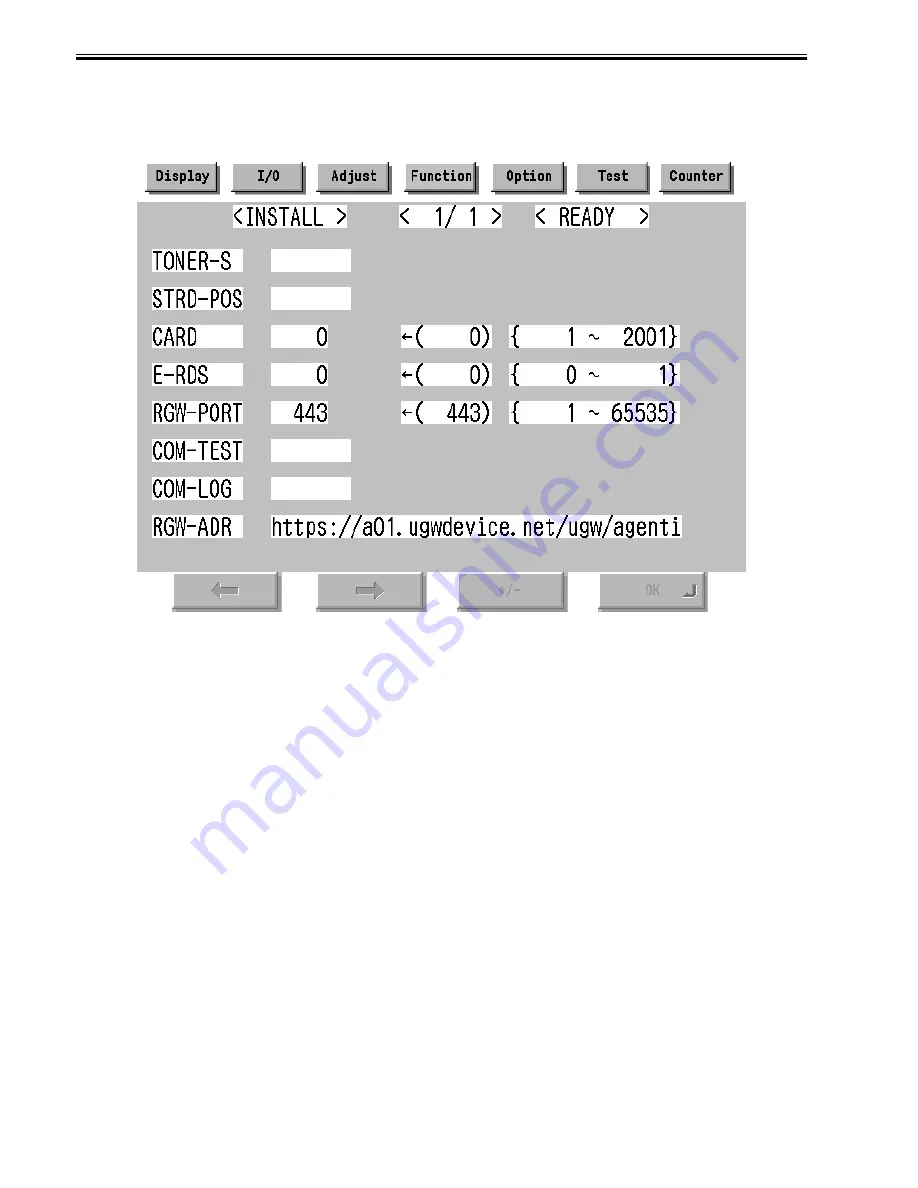
A-3. Display Menu screen of e-RDS
- Select (touch) [COPIER] > [Function] > [INSTALL] => Menu screen
F-12-4
B. Set 1 in [E-RDS].
C. Input the URL of UGW in [RGW-ADR]. (Select the input area to shift to the keyboard screen, and Input URL.)
D. Input the port number of UGW in [RGW-PORT].
E. Select [COM-TEST] and push [OK] button to start the communication test with UGW.
F. While the result is "NG!", repeat to correct the setting and try [COM-TEST] until the result becomes "OK!". You need checking the setting of the network of the
device and the connection of the network if necessary.
Notes: In the environment with the proxy server, you should set the proxy server. Refer to the proxy setting in the network guide of the device for details.
12.1.12 Trouble shoot
0016-1370
iR5065 / iR 5055 / iR5075 / iR5075N / iR5065N / iR5055N
1-1
Q. There is no setting item.
A. Confirm the network setting.
Confirm the model
1-2
Q. The communication test fails.
A. Confirm the firmware version.
Confirm the network setting.
Confirm the communication test result.
12.1.13 Error message
0016-1371
iR5065 / iR 5055 / iR5075 / iR5075N / iR5065N / iR5055N
Error information displayed in "Log list screen" or "Log detailed screen" is as follows.
Notes: Only the first part of error information is displayed in "Log list screen". Maximum length of error information in "Log detailed screen": 128 characters (not
include NULL)
When the communication test is not completed end e-RDS is 1 (ON), following string is displayed:
"SUSPEND: Communication test is not performed."
Summary of Contents for iR5055
Page 1: ...Feb 29 2008 Service Manual iR5075 5065 5055 Series ...
Page 2: ......
Page 6: ......
Page 27: ...Contents 19 1 2 List of Solvents Oils 19 2 ...
Page 28: ...Contents ...
Page 29: ...Chapter 1 Introduction ...
Page 30: ......
Page 32: ......
Page 59: ...Chapter 2 Installation ...
Page 60: ......
Page 104: ...Chapter 2 2 42 F 2 156 2 1 ...
Page 105: ...Chapter 3 Basic Operation ...
Page 106: ......
Page 108: ......
Page 115: ...Chapter 4 Main Controller ...
Page 116: ......
Page 118: ......
Page 135: ...Chapter 5 Original Exposure System ...
Page 136: ......
Page 169: ...Chapter 6 Laser Exposure ...
Page 170: ......
Page 172: ......
Page 178: ......
Page 179: ...Chapter 7 Image Formation ...
Page 180: ......
Page 184: ......
Page 217: ...Chapter 8 Pickup Feeding System ...
Page 218: ......
Page 274: ......
Page 275: ...Chapter 9 Fixing System ...
Page 276: ......
Page 280: ......
Page 320: ......
Page 321: ...Chapter 10 External and Controls ...
Page 322: ......
Page 326: ......
Page 336: ...Chapter 10 10 10 F 10 7 2 Remove the check mark from SNMP Status Enabled ...
Page 337: ...Chapter 10 10 11 F 10 8 ...
Page 361: ...Chapter 11 MEAP ...
Page 362: ......
Page 364: ......
Page 409: ...Chapter 12 e maintenance imageWARE Remote ...
Page 410: ......
Page 412: ......
Page 421: ...Chapter 13 Maintenance and Inspection ...
Page 422: ......
Page 424: ......
Page 433: ...Chapter 14 Standards and Adjustments ...
Page 434: ......
Page 464: ......
Page 465: ...Chapter 15 Correcting Faulty Images ...
Page 466: ......
Page 468: ......
Page 496: ......
Page 497: ...Chapter 16 Self Diagnosis ...
Page 498: ......
Page 500: ......
Page 528: ......
Page 529: ...Chapter 17 Service Mode ...
Page 530: ......
Page 532: ......
Page 600: ......
Page 601: ...Chapter 18 Upgrading ...
Page 602: ......
Page 604: ......
Page 636: ...Chapter 18 18 32 F 18 59 2 Select the data to download F 18 60 3 Click Start ...
Page 638: ......
Page 639: ...Chapter 19 Service Tools ...
Page 640: ......
Page 642: ......
Page 645: ...Feb 29 2008 ...
Page 646: ......


